Testing the electronic dash using rFactor required a method of transfering the game data to the Arduino. Fortunately creating custom displays for racing simulators has become a popular DIY hobby over the last few years. Therefore there are plenty of examples to be found online of various approaches. A great project by João Ubaldo provided detailed information and instructions for creating the display.
The Arduino is connected to the computer using a USB connection. Data is taken from the game using a plugin; converted to serial and then transfered to the Arduino where it is re-assembled. Initially I used the plugin rfactor2python which provided a great basis to improve on. This plugin is easy to install and modify as it is written using a language called python.
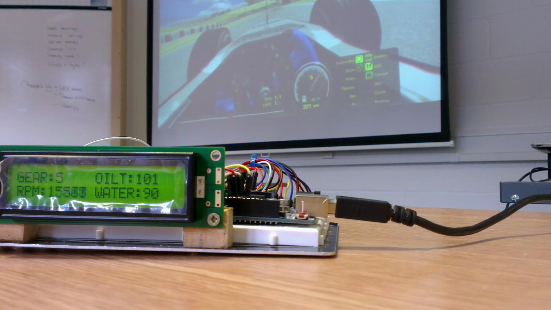
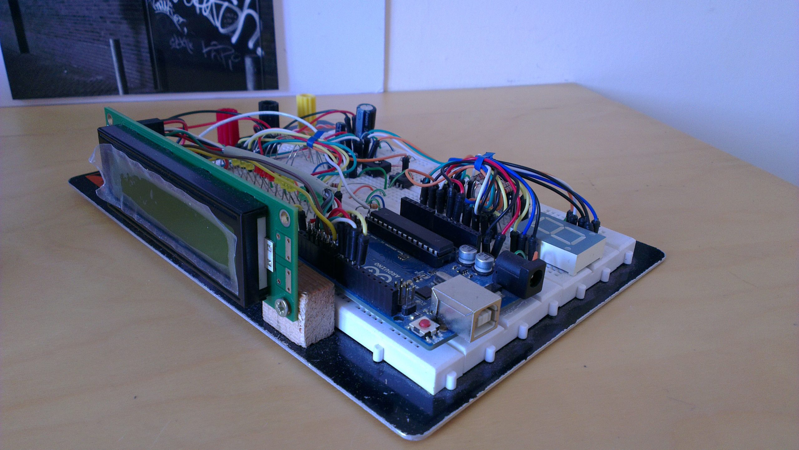
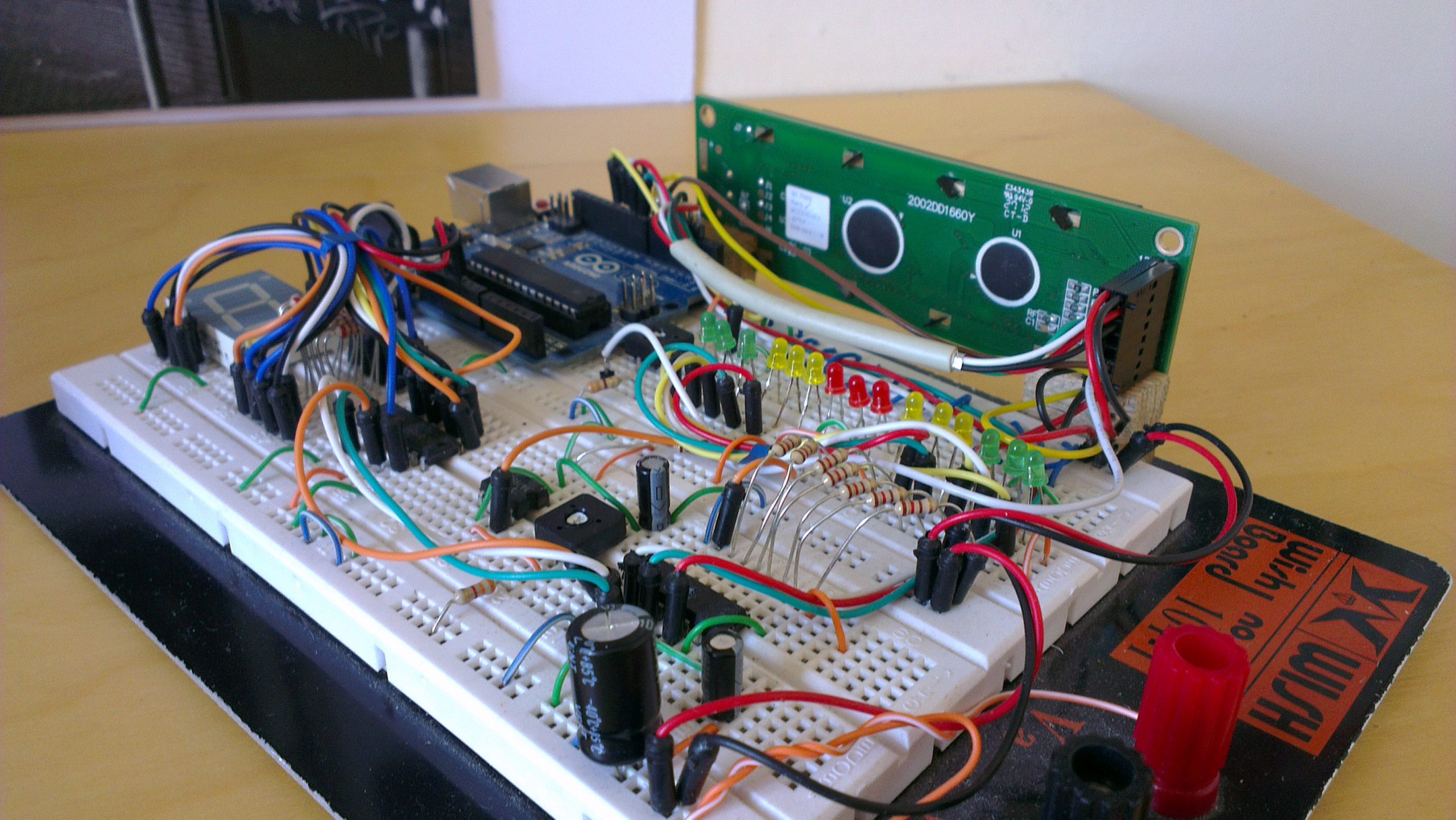
As I was using an LCD in addition to the 7 segment display and range of LEDs, a larger amount of data needed to be converted and transfered. This resulted in the following python plugin which breaks everything into byte sized chucks.
Python Serial
""" rfactor2python - UWE Racing Electronic Dash Test Credit: Joao C. <me@joaoubaldo.com> Author: D. Nicklin <danicklin.co.uk> This example uses PySerial (http://pyserial.sourceforge.net) module. """ # Configuration # Look inside RF2PyPlugin.__init__ # / import serial import struct class RF2PyPlugin(object): def __init__(self): self.PORT = "COM4" self.BPS = 9600 self.RPM_LED_COUNT = 7 # number of LEDs to display RPMs self.ser = None # game startup def Startup(self): pass # game shutdown def Shutdown(self): pass # entering realtime (where the vehicle can be driven) def EnterRealtime(self): self.ser = serial.Serial(self.PORT,self.BPS) # exiting realtime def ExitRealtime(self): self.ser.close() # session started def StartSession(self): pass # session ended def EndSession(self): pass # update plugin with scoring info (approximately once per second) # 'info' is a dictionary with scoring data def UpdateScoring(self, info): pass # update plugin with telemetry info # 'info' is a dictionary with telemetry data def UpdateTelemetry(self, info): g = info["mGear"] r = info["mEngineRPM"] mr = info["mEngineMaxRPM"] wt = info["mEngineWaterTemp"] ot = info["mEngineOilTemp"] val = struct.pack("I", r) g = g & 0xFF self.ser.write(chr(int(mr/1000))) self.ser.write(chr(int(g))) self.ser.write(chr(int(ot))) self.ser.write(chr(int(wt))) self.ser.write(val) self.ser.write('\n') # See if the plugin wants to take over a hardware control. If the plugin takes over the # control, this method returns true and sets the value of the float pointed to by the # second arg. Otherwise, it returns false and leaves the float unmodified. # # Important: fRetVal is a list with only one value. # In order to modify this value you should do something like: # fRetVal[0] = newValue def CheckHWControl(self, controlName, fRetVal): return FalseThe Arduino code reads the incoming serial data, byte by byte, these are placed into a buffer. The gear value is too large for a single byte and instead is split into four. The displays are refreshed every time it recieves a newline character. A little maths is performed to ensure that the full LED RPM range is utilised.
Arduino Sketch
/* UWE RACING Daniel Nicklin Formula Student Steering Wheel Display Reads data from rfactor using a python plugin Dsplays important variables on LCD, 7 segment and range of leds Created 26/03/2013 Last Modified 26/03/2013 */ void setup() { // Setup - run once //Serial Serial.begin(9600); } void loop() { while (Serial.available()) { char c = (char)Serial.read(); //Check for end of carriage if (c == '\n') { //asign values to variables rpmMaxValue =(buffer[0]*1000); newGear = constrain(buffer[1], -1, 7); // gear value between -1 (R) and 7 oilTemp = byte(buffer[2]); waterTemp = byte(buffer[3]); //Convert bytes in buffer to long integer for currrent rpm value union u_tag { byte b[4]; unsigned long ulval; } u; u.b[0] = buffer[4]; u.b[1] = buffer[5]; u.b[2] = buffer[6]; u.b[3] = buffer[7]; newRpmValue = u.ulval; //rpmLedLevel = (newRpmValue/(rpmMaxValue/7)); // Sets rpm value range for which leds are lit rpmLedStart = rpmMaxValue*0.8; //Sets minimum rpmMaxValue = rpmMaxValue * 1.05; //Game max value is set too low rpmLedLevel = map(constrain(newRpmValue,rpmLedStart,rpmMaxValue), rpmLedStart, rpmMaxValue, 0, 7); //Update shift registers if current gear or rpm has changed if (newGear != gear || newRpmValue != rpmValue){ digitalWrite(latchPin, LOW); //Pull latch LOW to start sending data shiftOut(dataPin, clockPin, MSBFIRST,gearArray[newGear]); //Send the data shiftOut(dataPin, clockPin, MSBFIRST,rpmArray[rpmLedLevel]); //Send the data digitalWrite(latchPin, HIGH); //Pull latch HIGH to stop sending data gear = newGear; rpmValue = newRpmValue; } pos = 0; //Reset position in buffer to start } else { //Add serial read data to buffer and increment position buffer[pos] = c; pos++; //check buffer size has not been exceeded if (pos >= sizeof(buffer)) pos = 0; } } }I attempted to display only the important sections of code in this post as there is rather a lot of it! I have attached the full code included start-up tests as a ZIP file. I’d be happy to know if you use this project and it’s code for Formula Student or a racing simulator of your own.
Requirements:
- An Arduino board and the Arduino IDE
- Python
- pyserial (Python Serial)
- The original rFactor plugin rFactor2Python Plugin
- My Updated plugin and Arduino Sketch Steering Wheel Display(.Zip)
