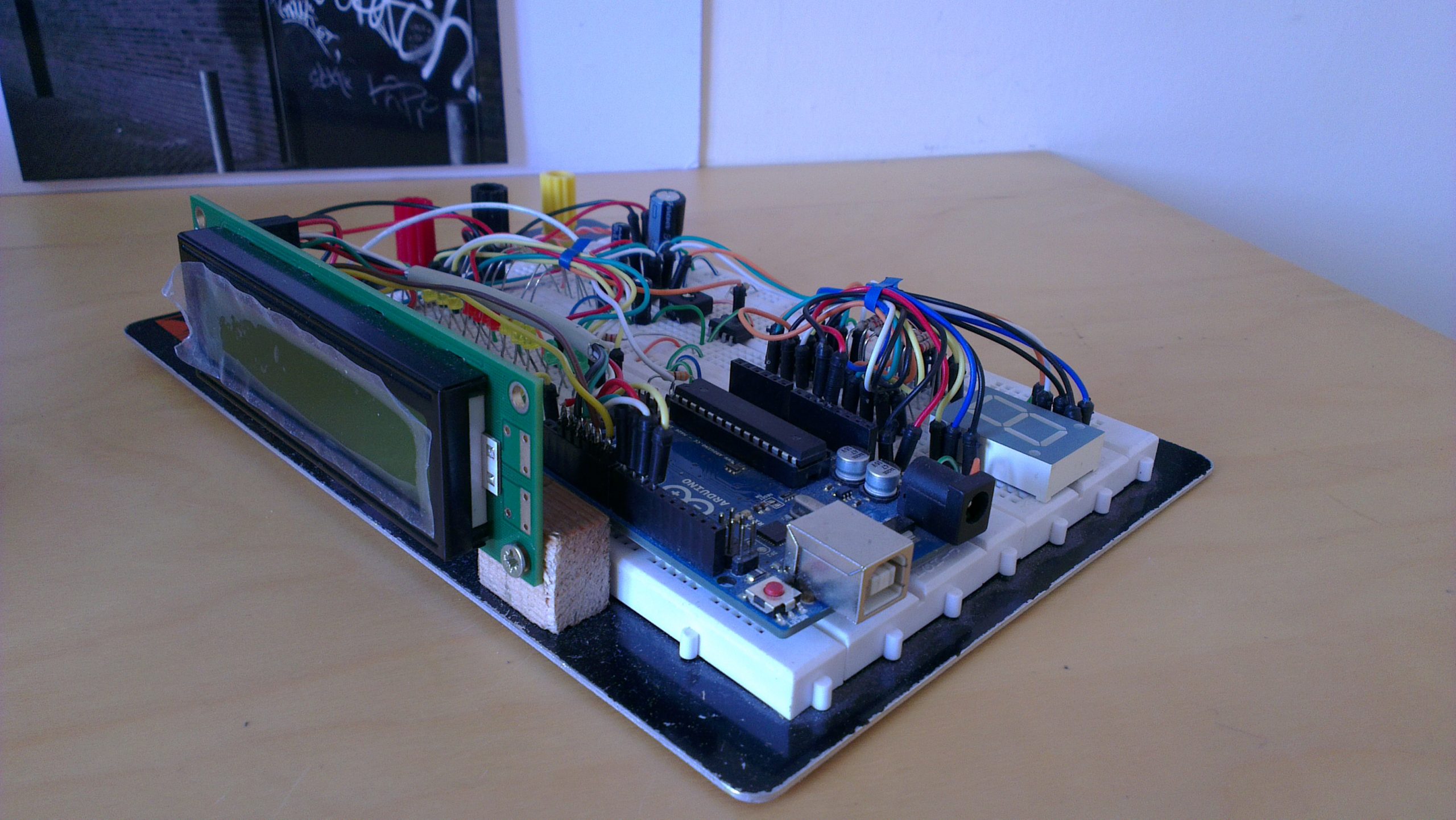
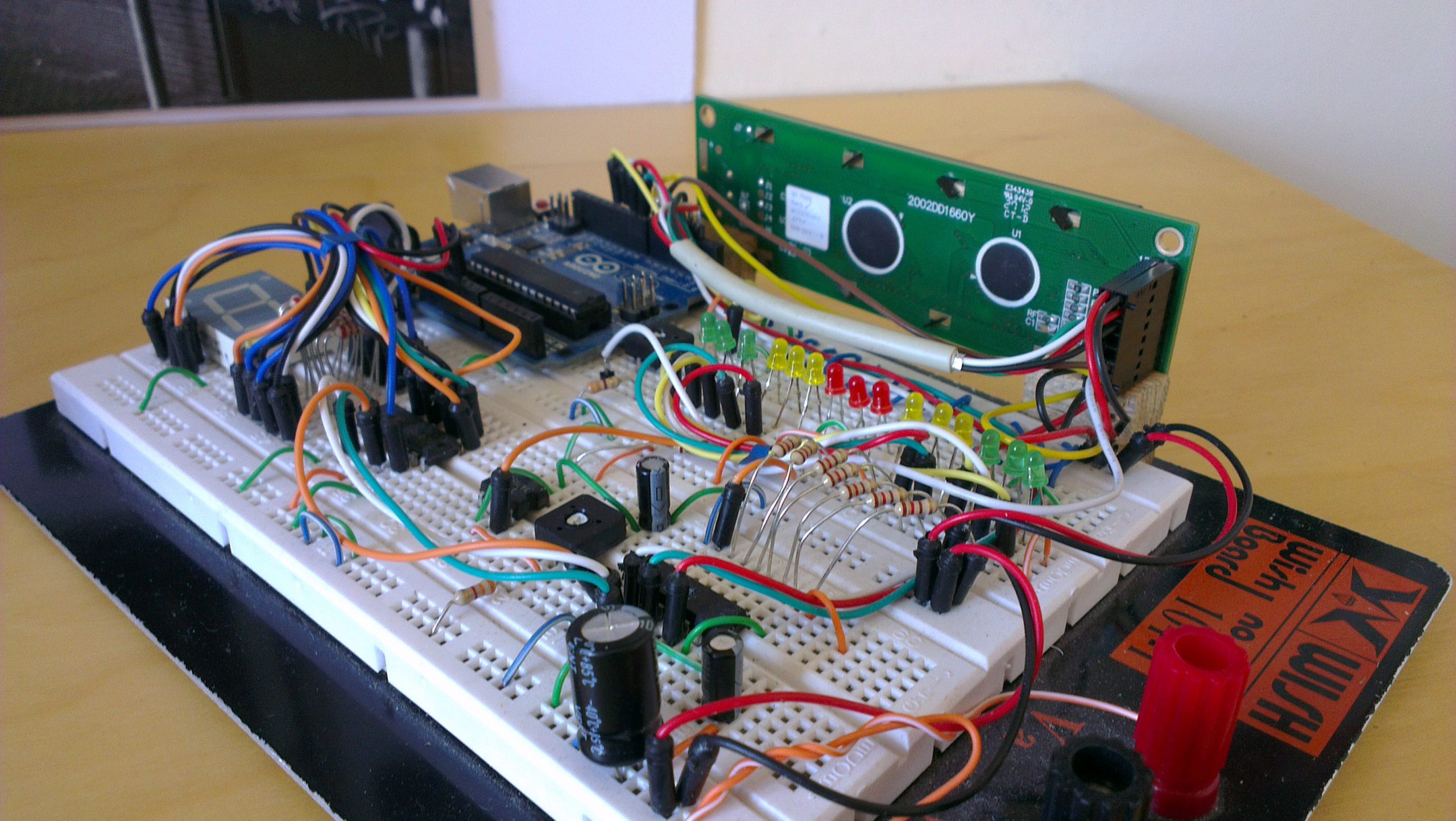
The steering wheel electronics were the first part of the steering wheel and electronic dash design to be researched and prototyped. The selected electronic components were assembled on a breadboard to allow for alterations to be made easily during the research and development stage of this project. As we didn’t have access to a running engine, the electronic dash was tested using car telemetry provided by the racing game rFactor.

Arduino
The Arduino Uno is an open-source microcontroller and simple I/O board. Due to its simplicity and low-cost it is a popular development environment for stand-alone and computer connected projects. Arduino is programmed using a Wiring-based language which is similar to C++.
RPM indicator
Located on either the top of the steering wheel or on the dash, a row of LEDs will represent the RPM range. The range will consist of a number of green, yellow and red LEDs and will light up from the outside inwards. Optional is the addition of a shift light.
Selected Gear Indicator
A 7 segment led display will be located in the middle of the steering wheel and be used to indicate the current gear. When no gear is selected (neutral) then “n.” will be displayed.
LCD Display
A small LCD display may be used to display important temperatures and current car states. This would be useful to the driver and car mechanics to monitor conditions without having to plug in a laptop. It will display a number of screen or menus that can be changed by directional buttons.
List of Steering Wheel Components
- RPM indication LED array (6 x Green, 6 x Yellow, 3 x Red)
- Selected gear indicator (0.8” Character size)
- LCD display (20 x 2)
- Warning LED (High Power Blue)
- Push Button