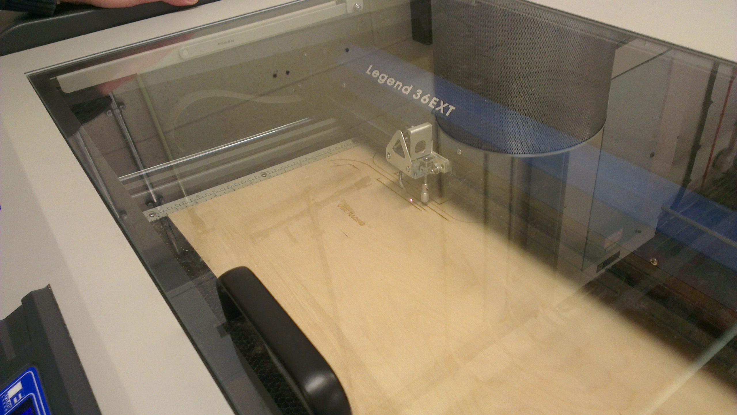
The steering wheel shape took inspiration from a product made by major FSAE manufacturer, Formula Seven. Using their dimensions and rough estimates of sizes for the chosen display components, the first prototype was laser cut from plywood. This prototype was mainly used to study the driver ergonomics and determine that the wheel was comfortable to hold.
Plasticine was used to quickly mold some example hand grips, instantly making the mock-up wheel more comfortable to hold. We altered thickness, radii and certain features such as thumb impressions to create a wheel that suited the majority of the team. Inspired by other formula student teams, we hoped to 3D scan these grips to create cad models. With some modification these could of been AM (additive manufacture) printed to create identical parts out of ABS plastic. Unfortuantely unable to source a 3D scanner by our target date, we instead created basic grips within Solidworks using measurements from the plasticine models.
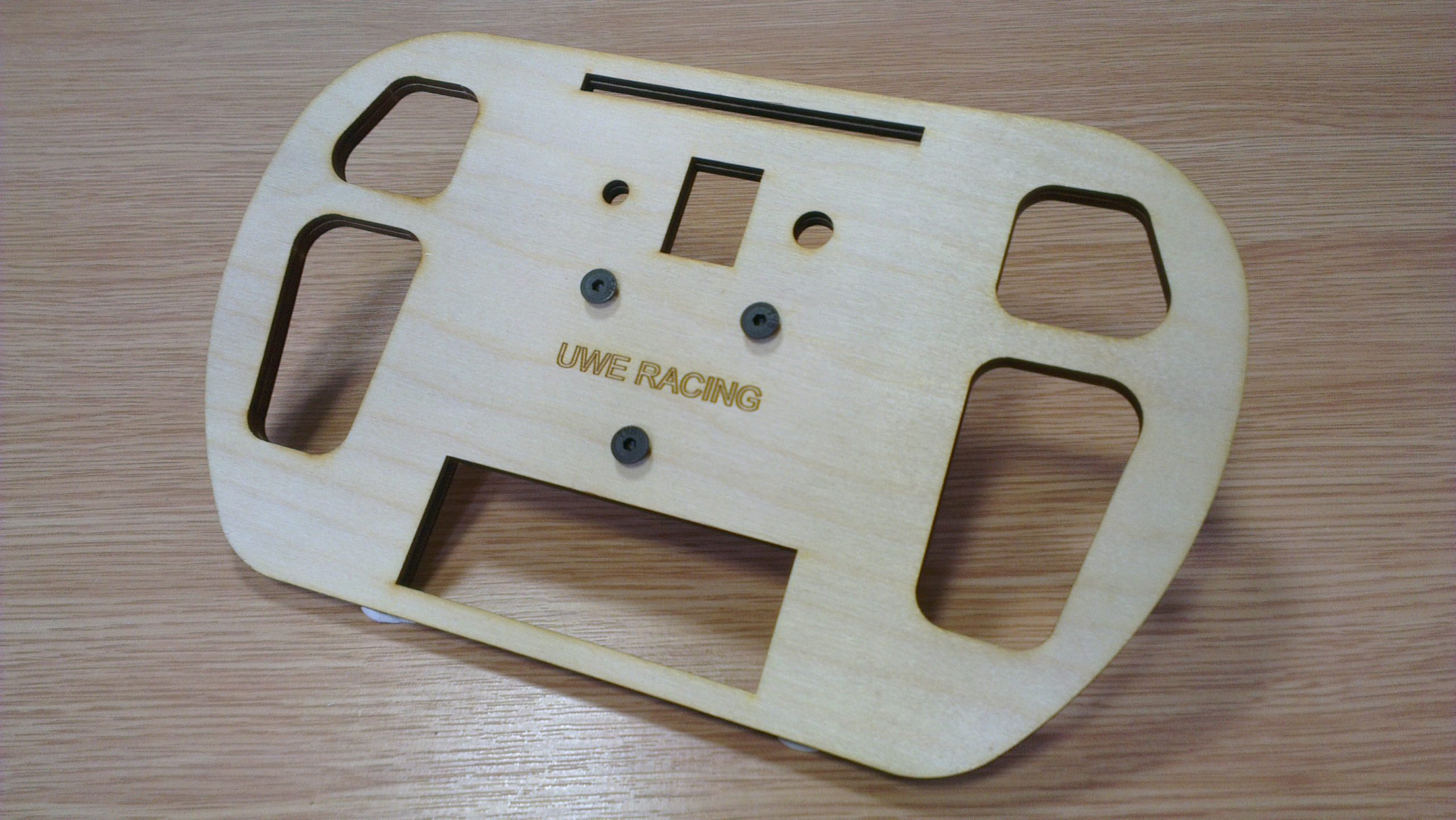
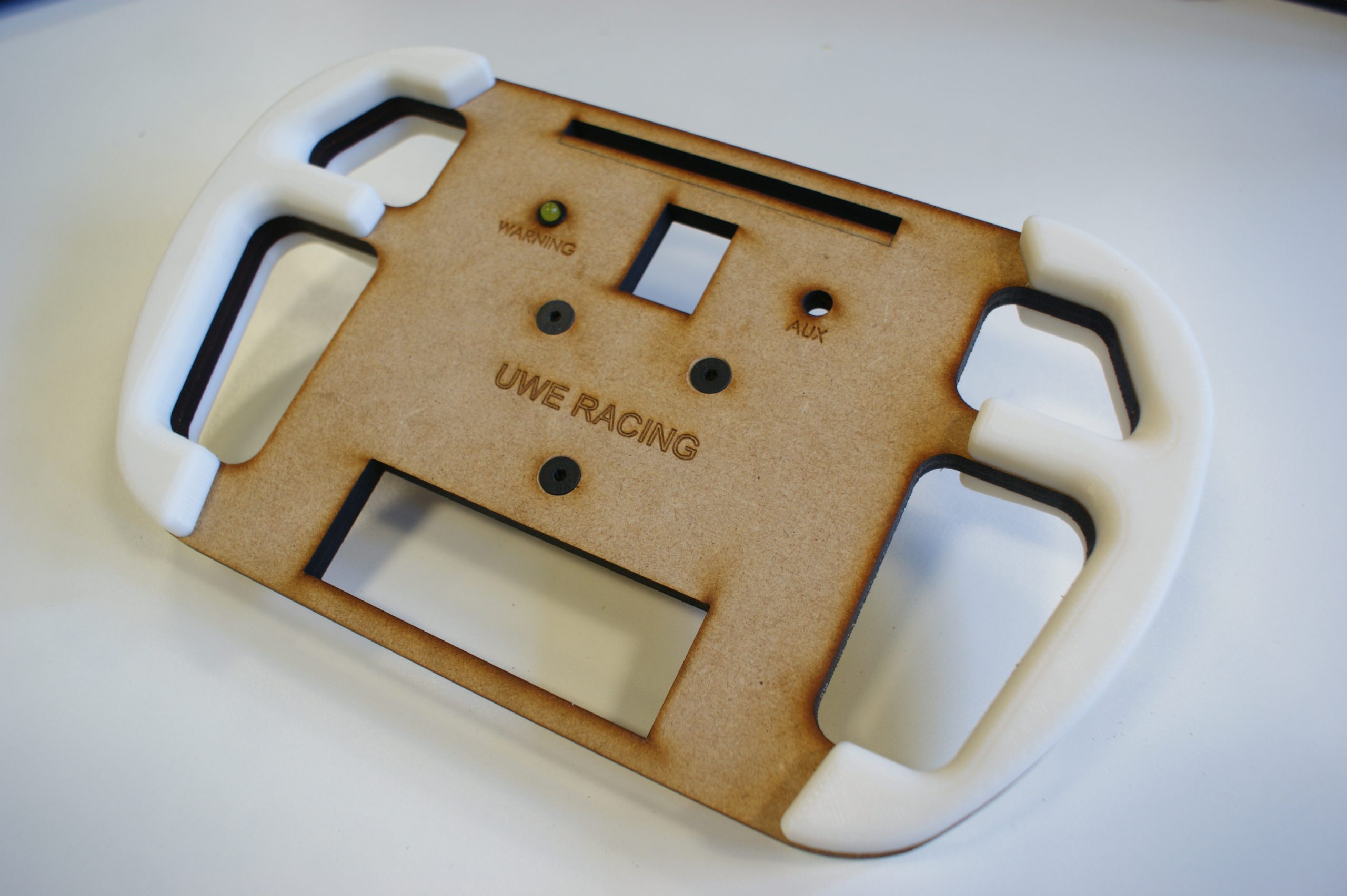
After determining the idea wheel width and hand hold dimensions, revision 2 was created. This also had the correct component dimensions, allowing us to partially assemble the wheel and check critical clearances. The finalised hand grips were temporarily attached. As predicted, the steering was put through it’s paces by all the team ( most making the necessary car noises).
Laser cutting plywood
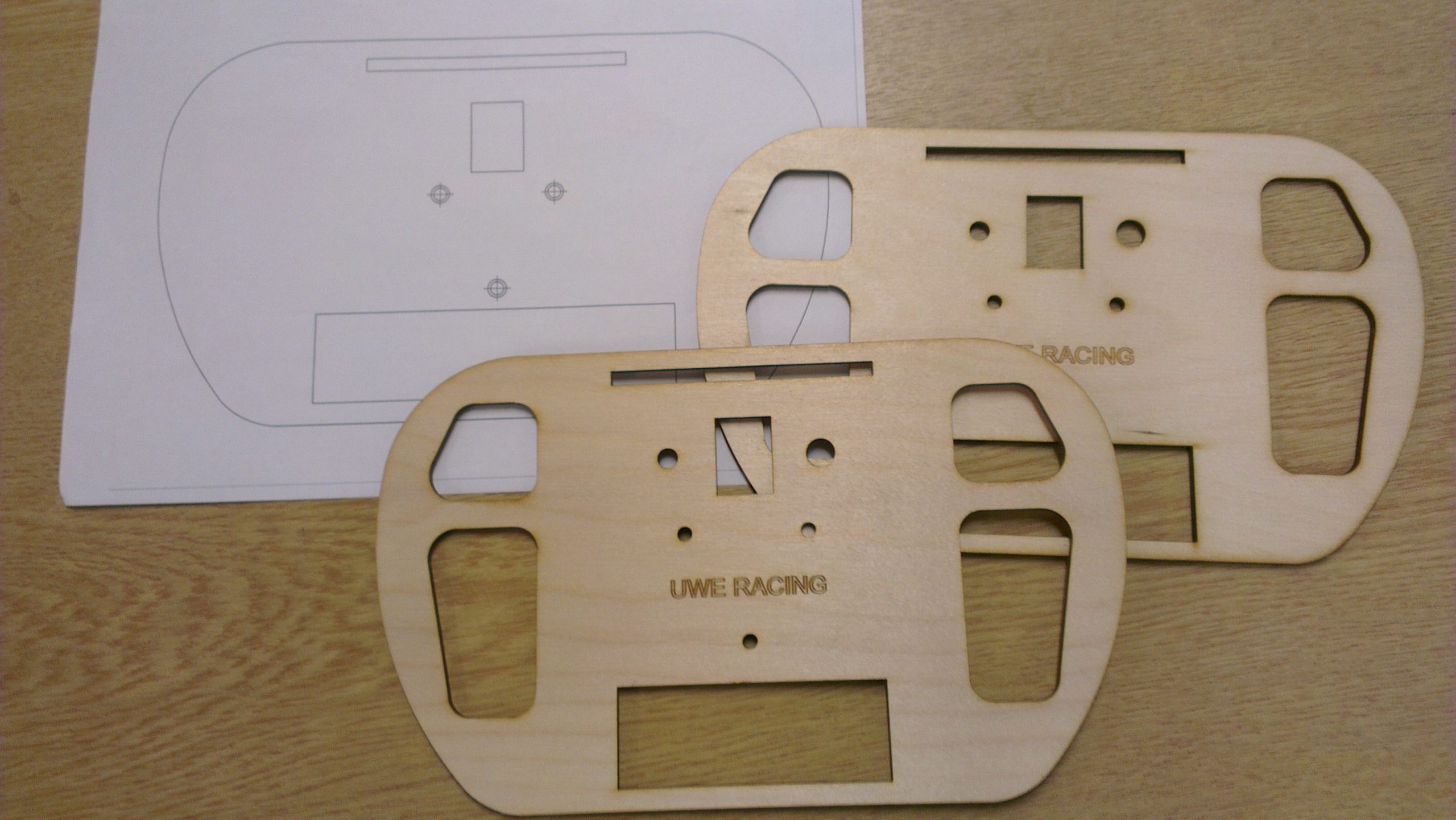
Prototype Revision-1 just after being cut
Prototype Revision-1 to be used for testing driver ergonomics
Plasticine was used so we could find the right handgrip shape
Revision-2 was cut from mdf with correct dimensions for electronic components
AM printed handgrips based on measurements from the molded plasticine
Testing the electronic dash using rFactor required a method of transfering the game data to the Arduino. Fortunately creating custom displays for racing simulators has become a popular DIY hobby over the last few years. Therefore there are plenty of examples to be found online of various approaches. A great project by João Ubaldo provided detailed information and instructions for creating the display.
The Arduino is connected to the computer using a USB connection. Data is taken from the game using a plugin; converted to serial and then transfered to the Arduino where it is re-assembled. Initially I used the plugin rfactor2python which provided a great basis to improve on. This plugin is easy to install and modify as it is written using a language called python.
Reposted image because there’s a metric **** tonne of code to follow…
As I was using an LCD in addition to the 7 segment display and range of LEDs, a larger amount of data needed to be converted and transfered. This resulted in the following python plugin which breaks everything into byte sized chucks.
Python Serial
"""
rfactor2python - UWE Racing Electronic Dash Test
Credit: Joao C. <me@joaoubaldo.com>
Author: D. Nicklin <danicklin.co.uk>
This example uses PySerial (http://pyserial.sourceforge.net) module.
"""
# Configuration
# Look inside RF2PyPlugin.__init__
# /
import serial
import struct
class RF2PyPlugin(object):
def __init__(self):
self.PORT = "COM4"
self.BPS = 9600
self.RPM_LED_COUNT = 7 # number of LEDs to display RPMs
self.ser = None
# game startup
def Startup(self):
pass
# game shutdown
def Shutdown(self):
pass
# entering realtime (where the vehicle can be driven)
def EnterRealtime(self):
self.ser = serial.Serial(self.PORT,self.BPS)
# exiting realtime
def ExitRealtime(self):
self.ser.close()
# session started
def StartSession(self):
pass
# session ended
def EndSession(self):
pass
# update plugin with scoring info (approximately once per second)
# 'info' is a dictionary with scoring data
def UpdateScoring(self, info):
pass
# update plugin with telemetry info
# 'info' is a dictionary with telemetry data
def UpdateTelemetry(self, info):
g = info["mGear"]
r = info["mEngineRPM"]
mr = info["mEngineMaxRPM"]
wt = info["mEngineWaterTemp"]
ot = info["mEngineOilTemp"]
val = struct.pack("I", r)
g = g & 0xFF
self.ser.write(chr(int(mr/1000)))
self.ser.write(chr(int(g)))
self.ser.write(chr(int(ot)))
self.ser.write(chr(int(wt)))
self.ser.write(val)
self.ser.write('\n')
# See if the plugin wants to take over a hardware control. If the plugin takes over the
# control, this method returns true and sets the value of the float pointed to by the
# second arg. Otherwise, it returns false and leaves the float unmodified.
#
# Important: fRetVal is a list with only one value.
# In order to modify this value you should do something like:
# fRetVal[0] = newValue
def CheckHWControl(self, controlName, fRetVal):
return False
The Arduino code reads the incoming serial data, byte by byte, these are placed into a buffer. The gear value is too large for a single byte and instead is split into four. The displays are refreshed every time it recieves a newline character. A little maths is performed to ensure that the full LED RPM range is utilised.
Arduino Sketch
/*
UWE RACING
Daniel Nicklin
Formula Student Steering Wheel Display
Reads data from rfactor using a python plugin
Dsplays important variables on LCD, 7 segment and range of leds
Created 26/03/2013
Last Modified 26/03/2013
*/
void setup() {
// Setup - run once
//Serial
Serial.begin(9600);
}
void loop() {
while (Serial.available()) {
char c = (char)Serial.read();
//Check for end of carriage
if (c == '\n') {
//asign values to variables
rpmMaxValue =(buffer[0]*1000);
newGear = constrain(buffer[1], -1, 7); // gear value between -1 (R) and 7
oilTemp = byte(buffer[2]);
waterTemp = byte(buffer[3]);
//Convert bytes in buffer to long integer for currrent rpm value
union u_tag {
byte b[4];
unsigned long ulval;
} u;
u.b[0] = buffer[4];
u.b[1] = buffer[5];
u.b[2] = buffer[6];
u.b[3] = buffer[7];
newRpmValue = u.ulval;
//rpmLedLevel = (newRpmValue/(rpmMaxValue/7));
// Sets rpm value range for which leds are lit
rpmLedStart = rpmMaxValue*0.8; //Sets minimum
rpmMaxValue = rpmMaxValue * 1.05; //Game max value is set too low
rpmLedLevel = map(constrain(newRpmValue,rpmLedStart,rpmMaxValue), rpmLedStart, rpmMaxValue, 0, 7);
//Update shift registers if current gear or rpm has changed
if (newGear != gear || newRpmValue != rpmValue){
digitalWrite(latchPin, LOW); //Pull latch LOW to start sending data
shiftOut(dataPin, clockPin, MSBFIRST,gearArray[newGear]); //Send the data
shiftOut(dataPin, clockPin, MSBFIRST,rpmArray[rpmLedLevel]); //Send the data
digitalWrite(latchPin, HIGH); //Pull latch HIGH to stop sending data
gear = newGear;
rpmValue = newRpmValue;
}
pos = 0; //Reset position in buffer to start
}
else {
//Add serial read data to buffer and increment position
buffer[pos] = c;
pos++;
//check buffer size has not been exceeded
if (pos >= sizeof(buffer))
pos = 0;
}
}
}
I attempted to display only the important sections of code in this post as there is rather a lot of it! I have attached the full code included start-up tests as a ZIP file. I’d be happy to know if you use this project and it’s code for Formula Student or a racing simulator of your own.
The steering wheel electronics were the first part of the steering wheel and electronic dash design to be researched and prototyped. The selected electronic components were assembled on a breadboard to allow for alterations to be made easily during the research and development stage of this project. As we didn’t have access to a running engine, the electronic dash was tested using car telemetry provided by the racing game rFactor.
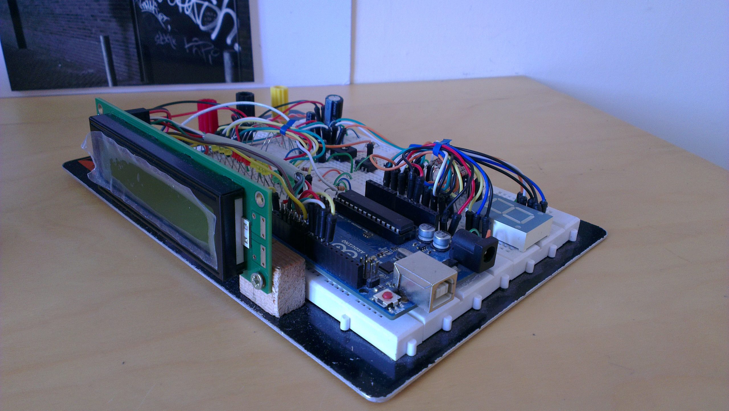
Breadboard Assembly showing LCD and Arduino
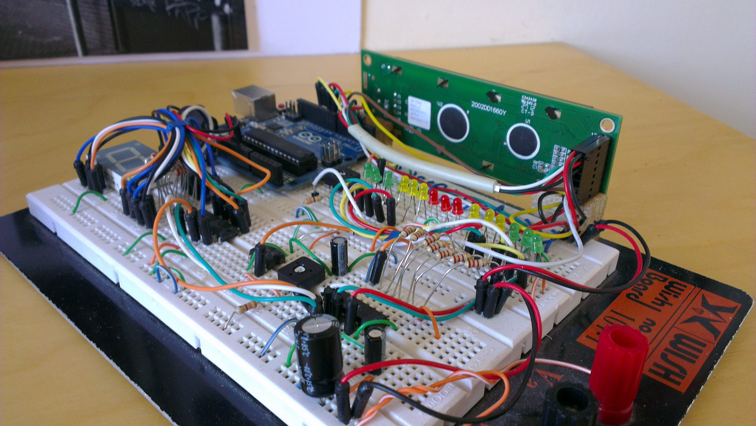
Breadboard Assembly showing the RPM LED range powered by a shift register
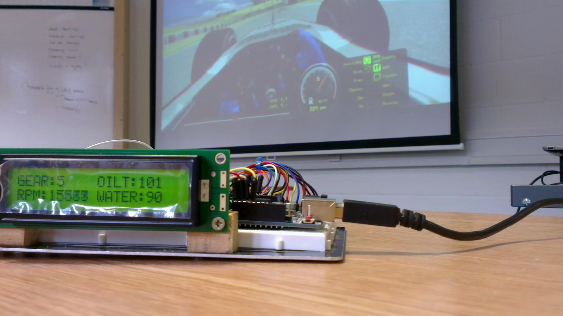
Breadboard assembled electronics being tested using rFactor for input data
Arduino
The Arduino Uno is an open-source microcontroller and simple I/O board. Due to its simplicity and low-cost it is a popular development environment for stand-alone and computer connected projects. Arduino is programmed using a Wiring-based language which is similar to C++.
RPM indicator
Located on either the top of the steering wheel or on the dash, a row of LEDs will represent the RPM range. The range will consist of a number of green, yellow and red LEDs and will light up from the outside inwards. Optional is the addition of a shift light.
Selected Gear Indicator
A 7 segment led display will be located in the middle of the steering wheel and be used to indicate the current gear. When no gear is selected (neutral) then “n.” will be displayed.
LCD Display
A small LCD display may be used to display important temperatures and current car states. This would be useful to the driver and car mechanics to monitor conditions without having to plug in a laptop. It will display a number of screen or menus that can be changed by directional buttons.
List of Steering Wheel Components
RPM indication LED array (6 x Green, 6 x Yellow, 3 x Red)