Category Archives: Formula Student

UWE Formula Student consists of a team of highly motivated students who are striving for success in the international Formula Student competition. As an extra-curricular activity, it provides a great opportunity for practical application to students studying a variety of degree disciplines.

During my time at University, I worked on many different parts of the project including electrical systems, website design and media.

Steering Wheel – Electronic Design and Assembly

The task of designing the PCB, to be mounted to the steering wheel assembly, proved to be tough. With only some experience from GCSE electronics, this part of the project was accompanied with a steep learning curve.

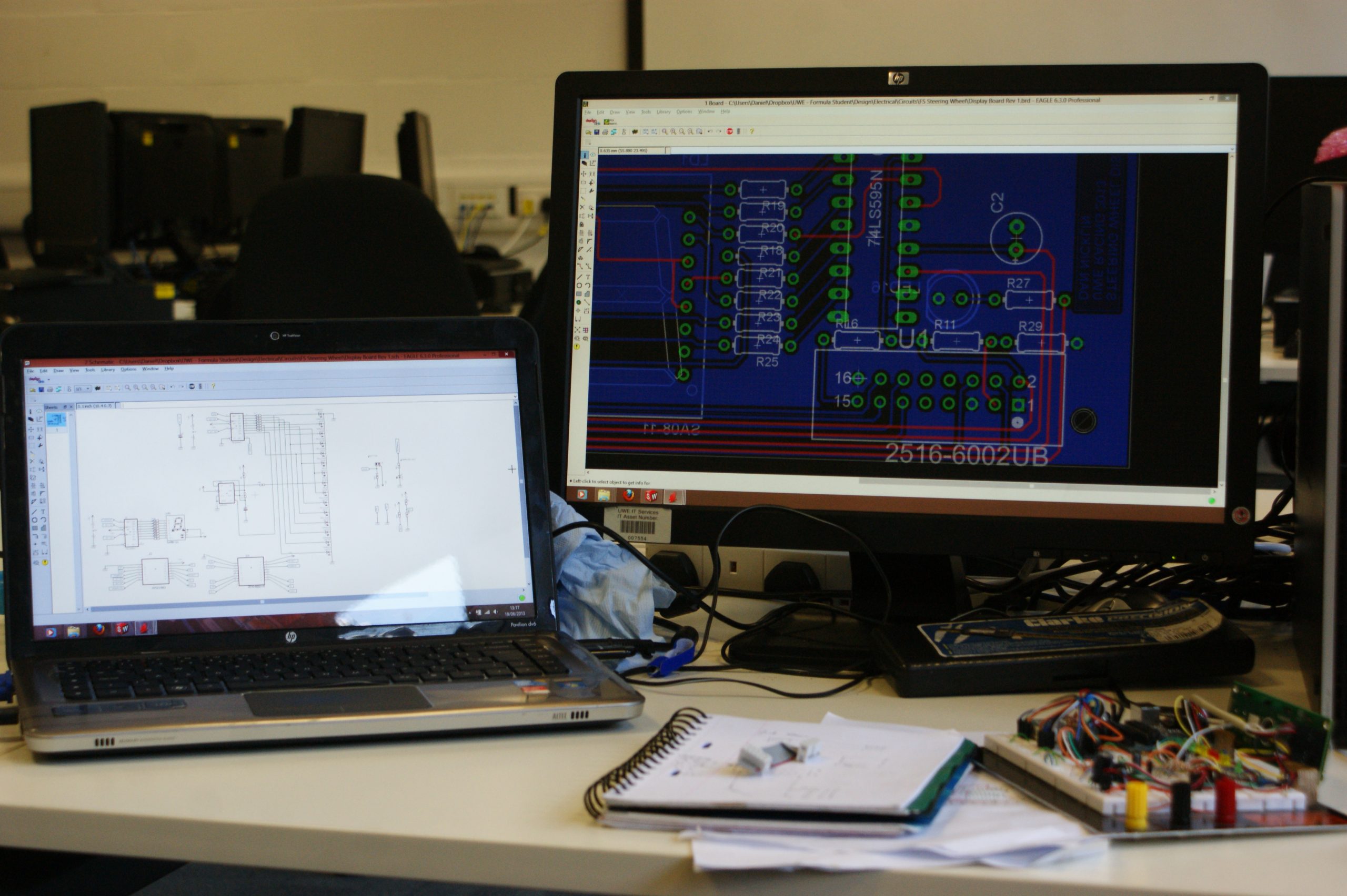
Through recommendation on a number of Arduino forums, the software of choice was Eagle v6 from CadSoft. This is a powerful tool with an extensive library of electronic components. The user interface wasn’t the most user friendly, instead relying on keyboard shortcuts. Although it was easy to learn by following a selection of YouTube tutorials by Jeremy Blum.

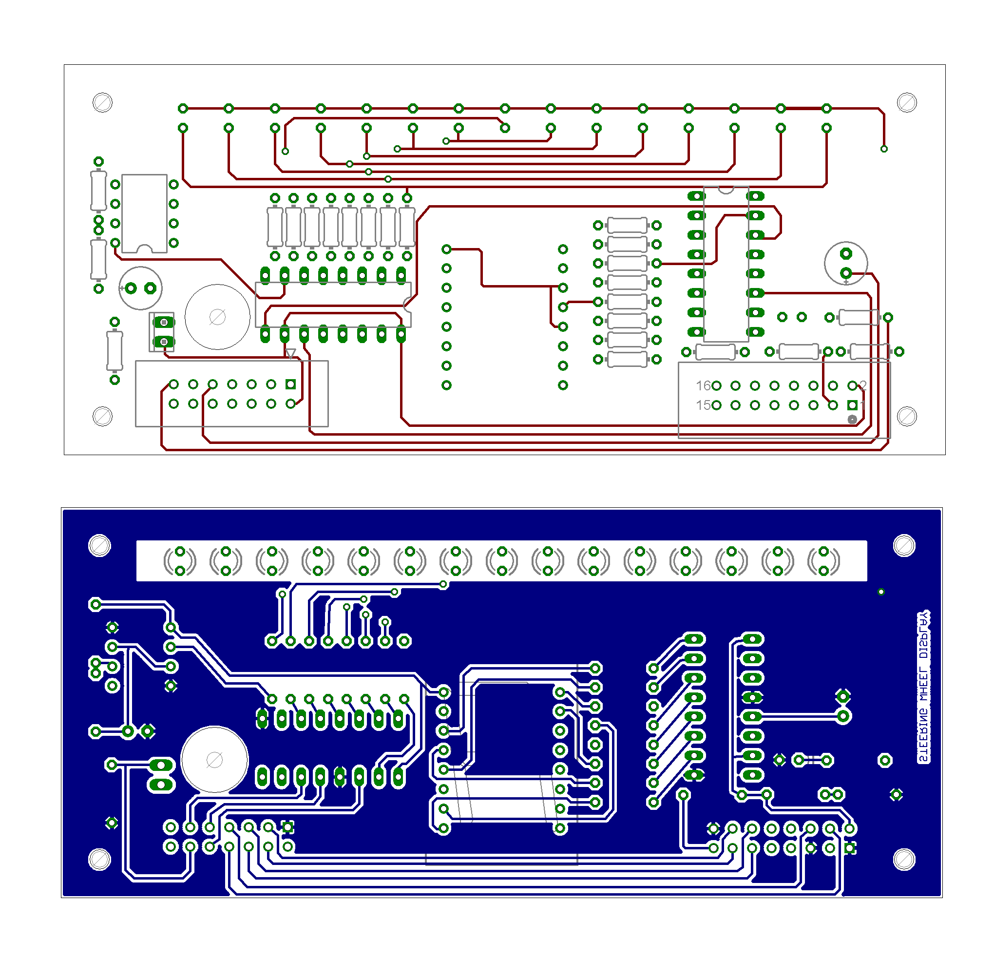
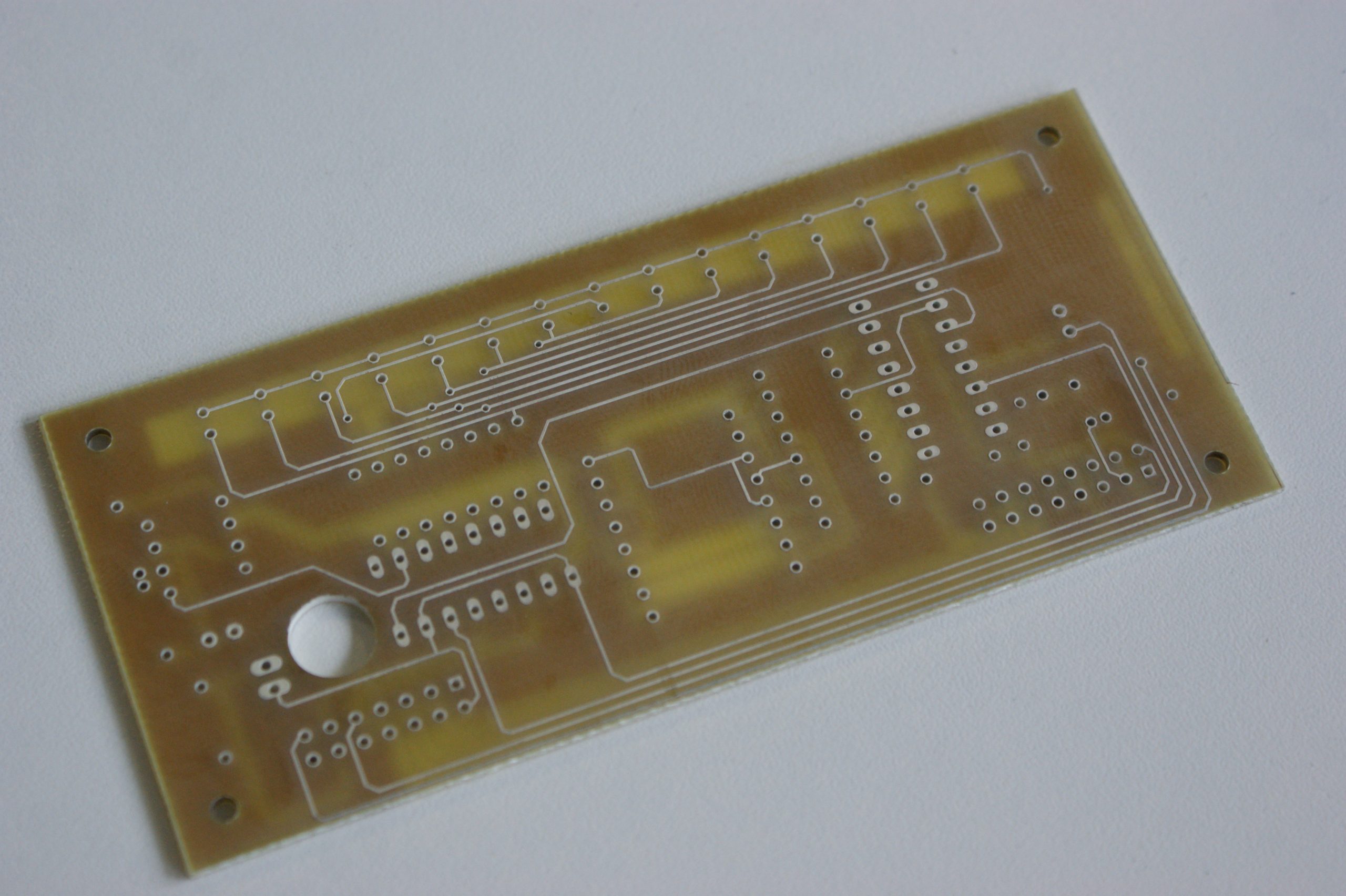
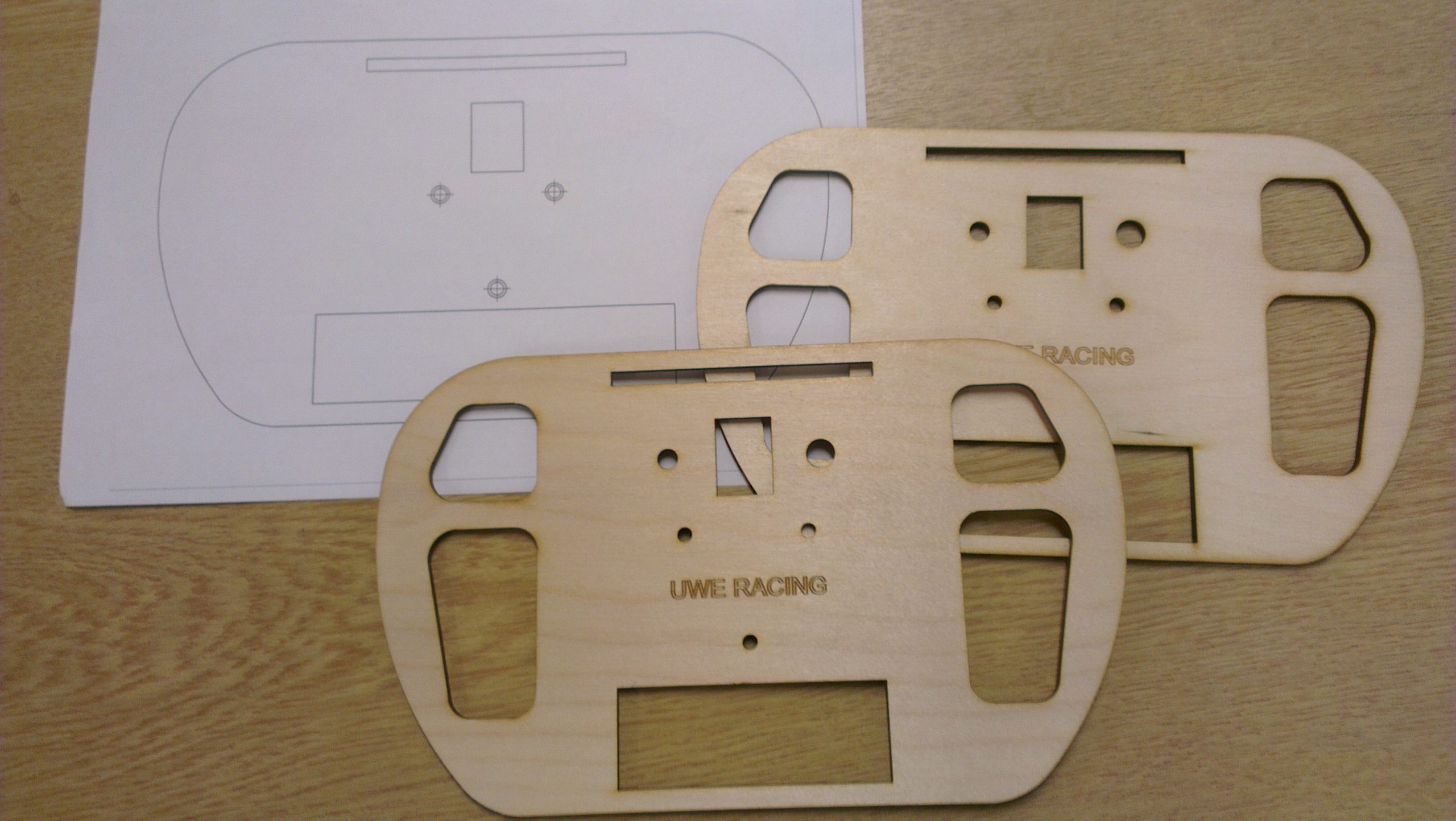
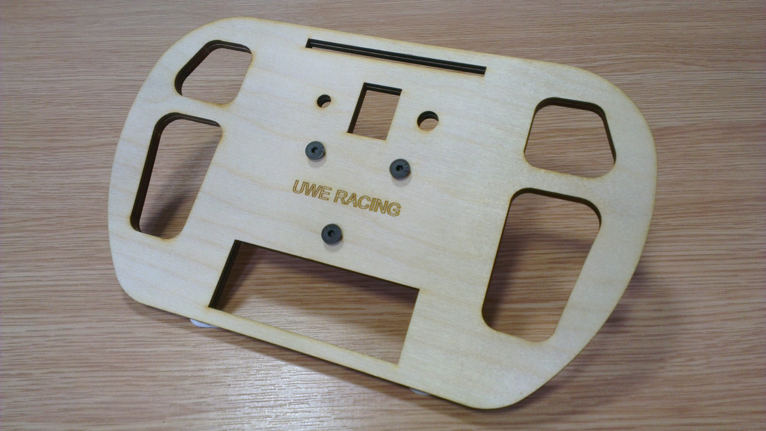
The size of the board (51mm x 110mm) was dictated by the space available between the top of the steering wheel and the steering boss, leaving adequate clearance for covers. Placement of the display components upon the board were already decided. This left only the other electrical components and tracks to be placed and routed.

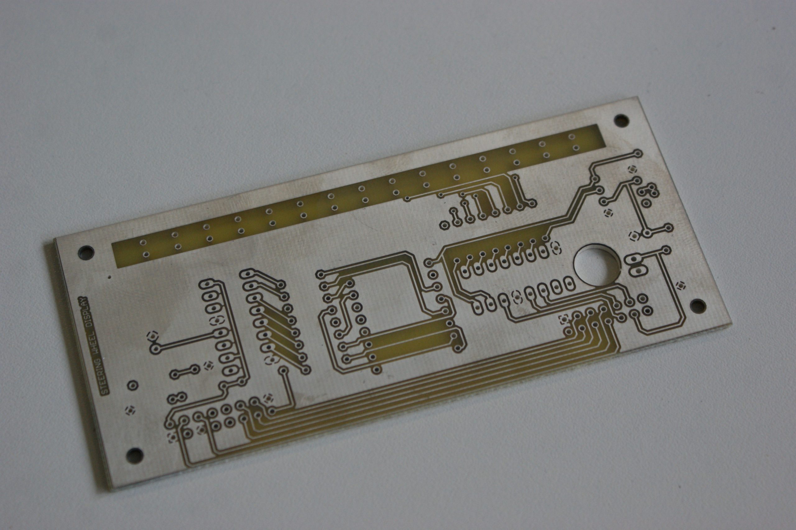
The board was fabricated by Spirit Circuits and their free 48-hour prototyping service “Go Naked”. They provided us with a two sided aluminium coated board with just the essentials, tracks and holes. Their customer service was exceptional in helping to meet our needs. We promptly received a professional high quality board that only required cutting to size prior to use.

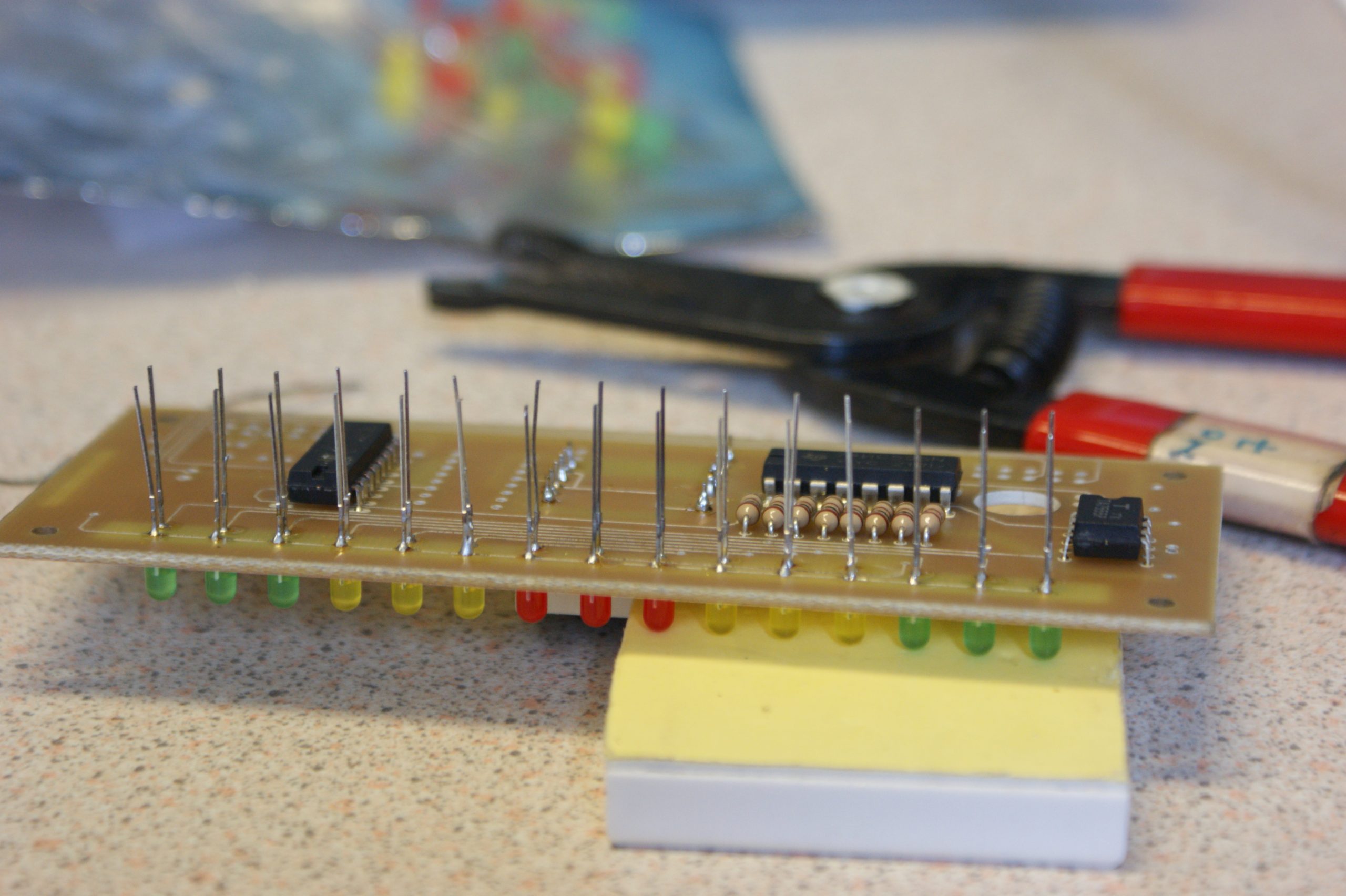
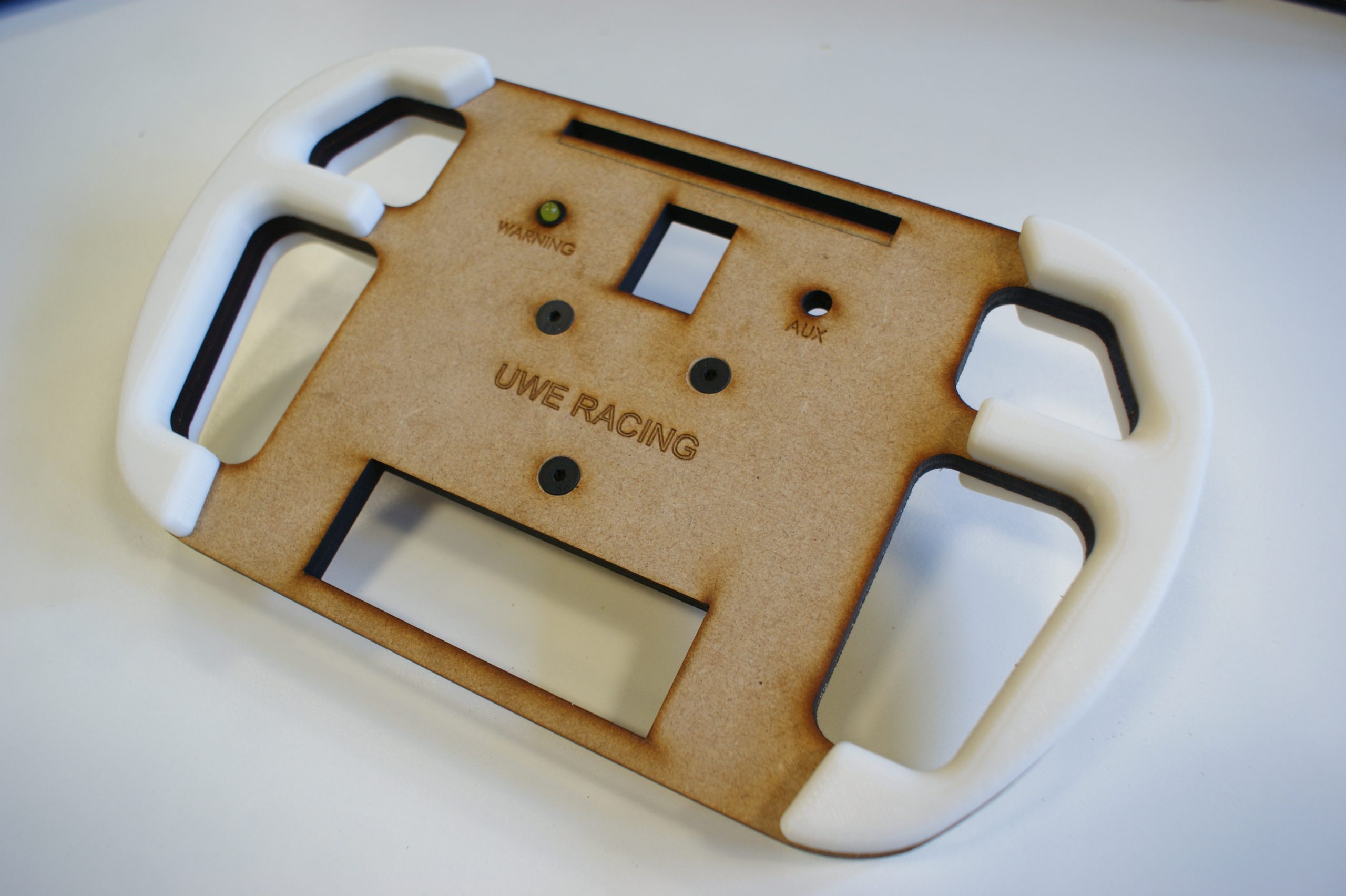
Initially the assembly and soldering of the electronic dash went to plan, with the majority of the components fitting without a problem. A couple of overlooks included; attachment of the switch and warning LED, placement of the ribbon cable and selection of connectors.

When linked to the Arduino and powered for the first time, all of the display lit up and ran through the start-up test routine a few times. But before too long, it was noticeable that the display was not functioning entirely correctly. The central RPM range LED failed to blink and the LCD display would occasionally flicker with random characters. This suggested that either a faulty component had been used or the board was shorting. After inspecting the soldering and replacing components, it was found that a grounding fault was the cause. Although it’s exact location was unknown.

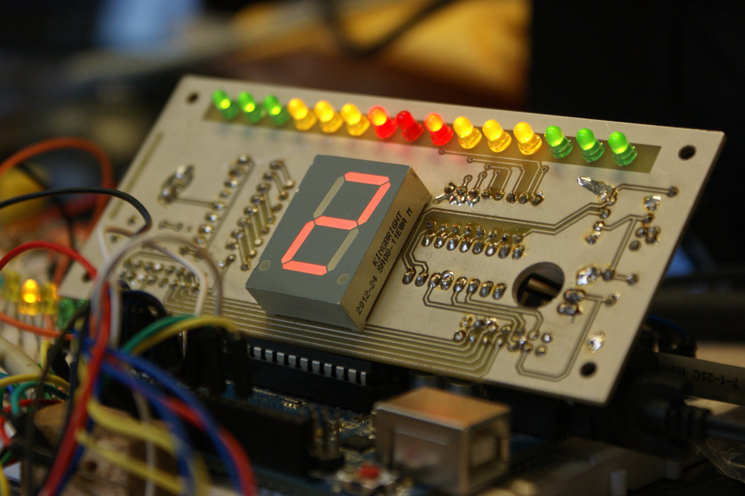
While it was disappointing that the display did not work correctly. It proved to be a great prototype and provided us with a number of improvements for the next revision. The main points being; bigger tracks, pads and clearances along with smaller components.

Next… Steering Wheel – Final Assembly

Steering Wheel – FEA

Whilst designing the wheel shape in Solidworks, there was uncertaintly around material choice and plate thickness. Within the university we had a selection of sheet metal, including steel and aluminium. Fortunately during research we stumbled upon a document concerning driver contol requirements by FSAE judge, Steve Fox.

Minimum driver applied forces, you should be designing/building/testing for:

  • Steering System Lateral Force – The steering wheel and steering column should be able to withstand at least 660 N (150 lb) lateral (radial) force before failure.
  • Steering System Torque – The steering system should be able to withstand a minimum of 100 Nm (75 ft lb) force, applied at the steering wheel, before failure.

Using these forces and FEA (Finite Element Analysis), the main plate was subject to numerous load tests with a variety of materials and thicknesses. The results for von mises stress and displacement observed in these load tests were studied to decide which material and thickness was most ideal.

This slideshow requires JavaScript.

Unfortunately this process was rushed and carried out with little thought of overall mass. Our selected material, Aluminium 5083 with a thickness of 6mm, resulted in a total assembly mass of around 800 grams. This was considerably heavier than alternative off-the-shelf steering wheels with electronic displays which tended to be around 400-500 grams in total. As mass is an incredibly important factor for Formula Student cars, the design would have to be revised and lightened before another wheel is made.

Steering Wheel – Design and Development

The steering wheel shape took inspiration from a product made by major FSAE manufacturer, Formula Seven. Using their dimensions and rough estimates of sizes for the chosen display components, the first prototype was laser cut from plywood. This prototype was mainly used to study the driver ergonomics and determine that the wheel was comfortable to hold.

Plasticine was used to quickly mold some example hand grips, instantly making the mock-up wheel more comfortable to hold. We altered thickness, radii and certain features such as thumb impressions to create a wheel that suited the majority of the team. Inspired by other formula student teams, we hoped to 3D scan these grips to create cad models. With some modification these could of been AM (additive manufacture) printed to create identical parts out of ABS plastic. Unfortuantely unable to source a 3D scanner by our target date, we instead created basic grips within Solidworks using measurements from the plasticine models.

After determining the idea wheel width and hand hold dimensions, revision 2 was created. This also had the correct component dimensions, allowing us to partially assemble the wheel and check critical clearances. The finalised hand grips were temporarily attached. As predicted, the steering was put through it’s paces by all the team ( most making the necessary car noises).

Next… Steering Wheel – FEA Load Testing