Formula Student – Pedalbox

This is a rather late post considering that I carried out the work over the summer period. During the Formula Student competition in July, we entered our first Class 1 car. Through a tremendous amount effort, determination and many late nights we took a near completed, but not yet run car to the event. There were many parts of the car that still required assembly, some that needed to be altered to meet the strict scrutineering and nearly all were untested…

One of the major systems that did not get any much needed testing before the event were the brakes, this proved to be our Achilles heel. During the final scrutineering event which was the brake test, even after multiple attempts we still failed to lock up all four wheels. There was a lack of pressure in the braking system, which was due to flexibility in the pedalbox. During the event we had made numerous attempts to strengthen the assembly using whatever scraps of metal we could find and weld on. Unfortunately this was not enough and we ended up damaging the pedalbox in the final brake test.

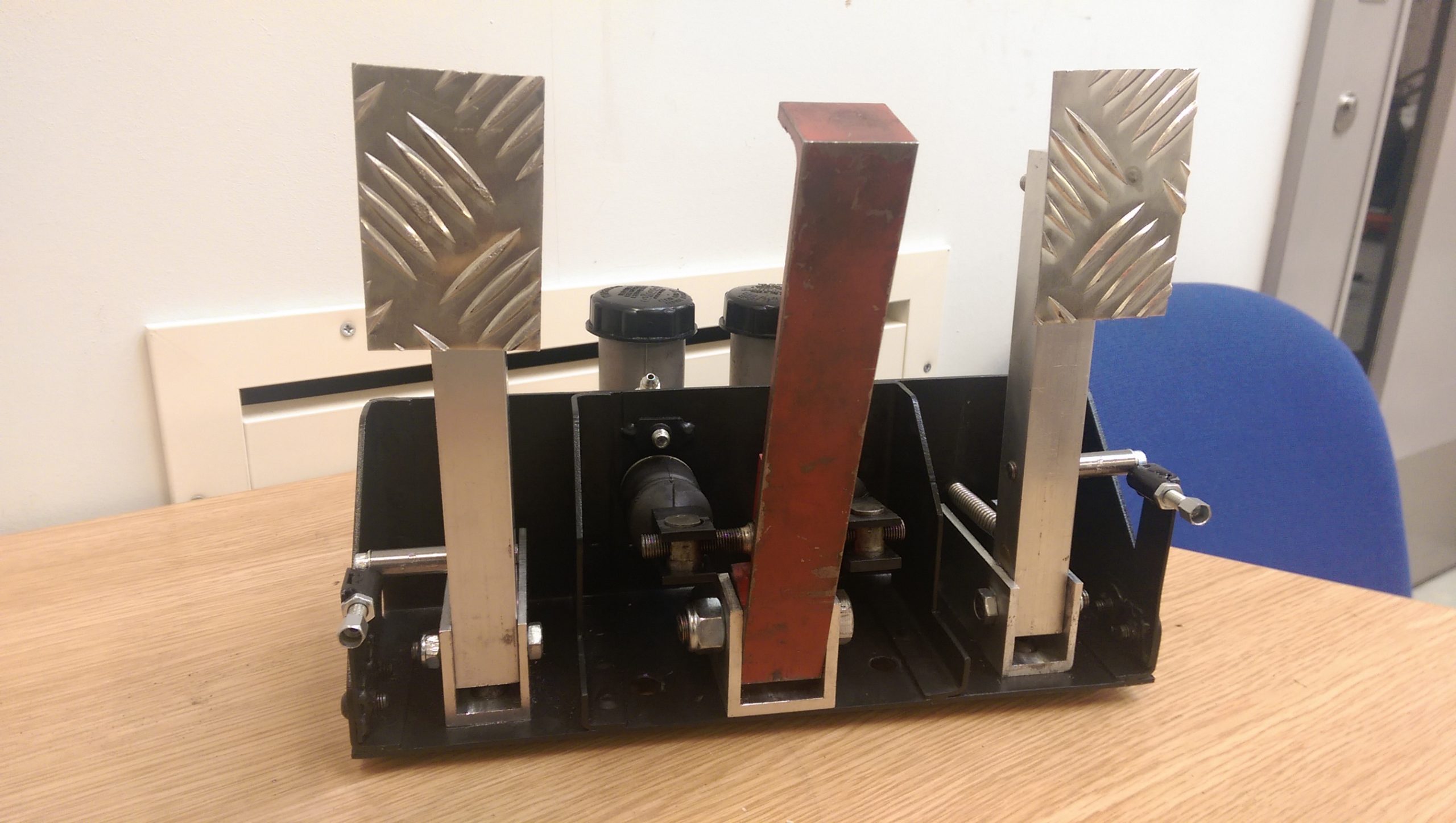
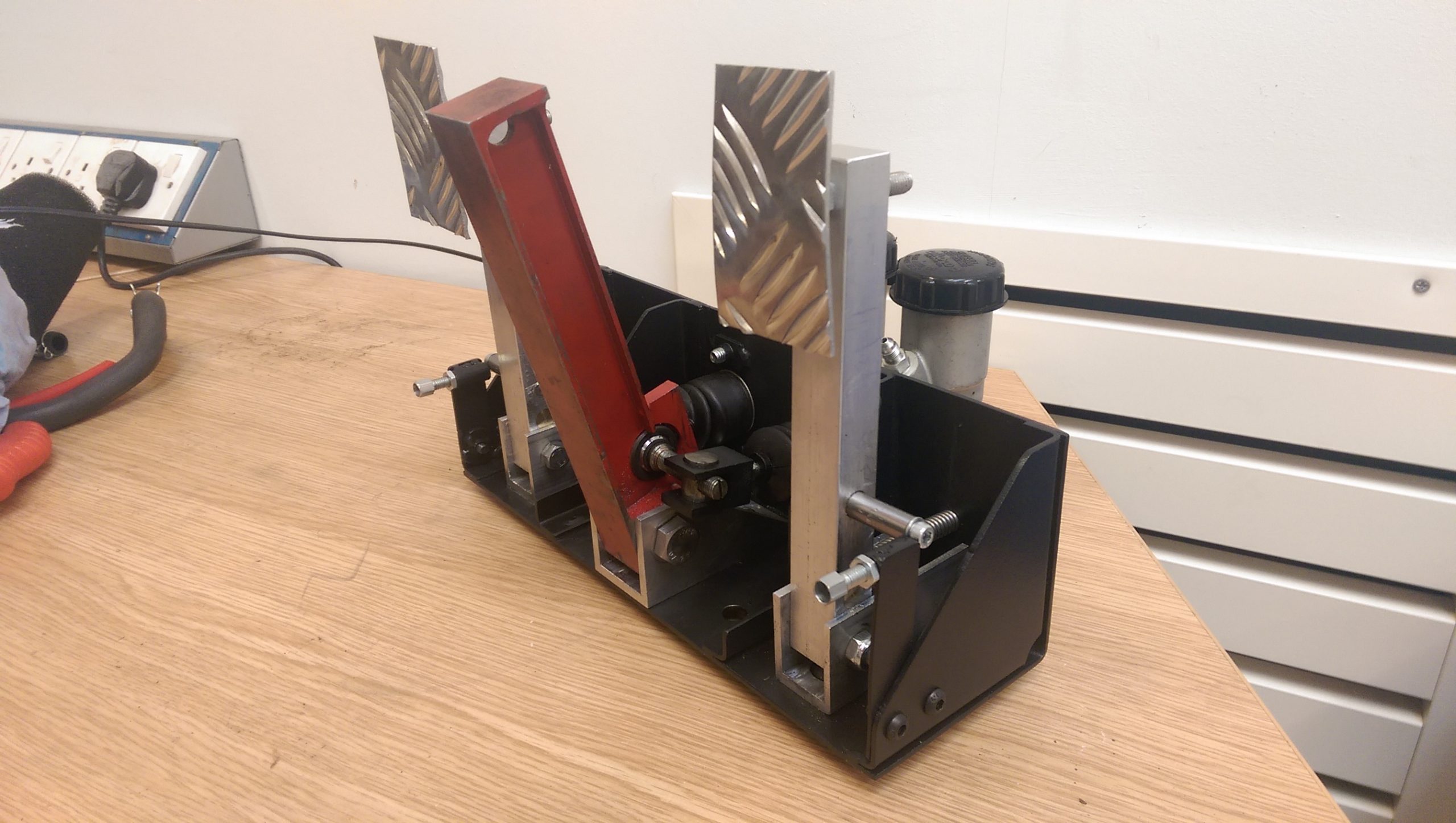
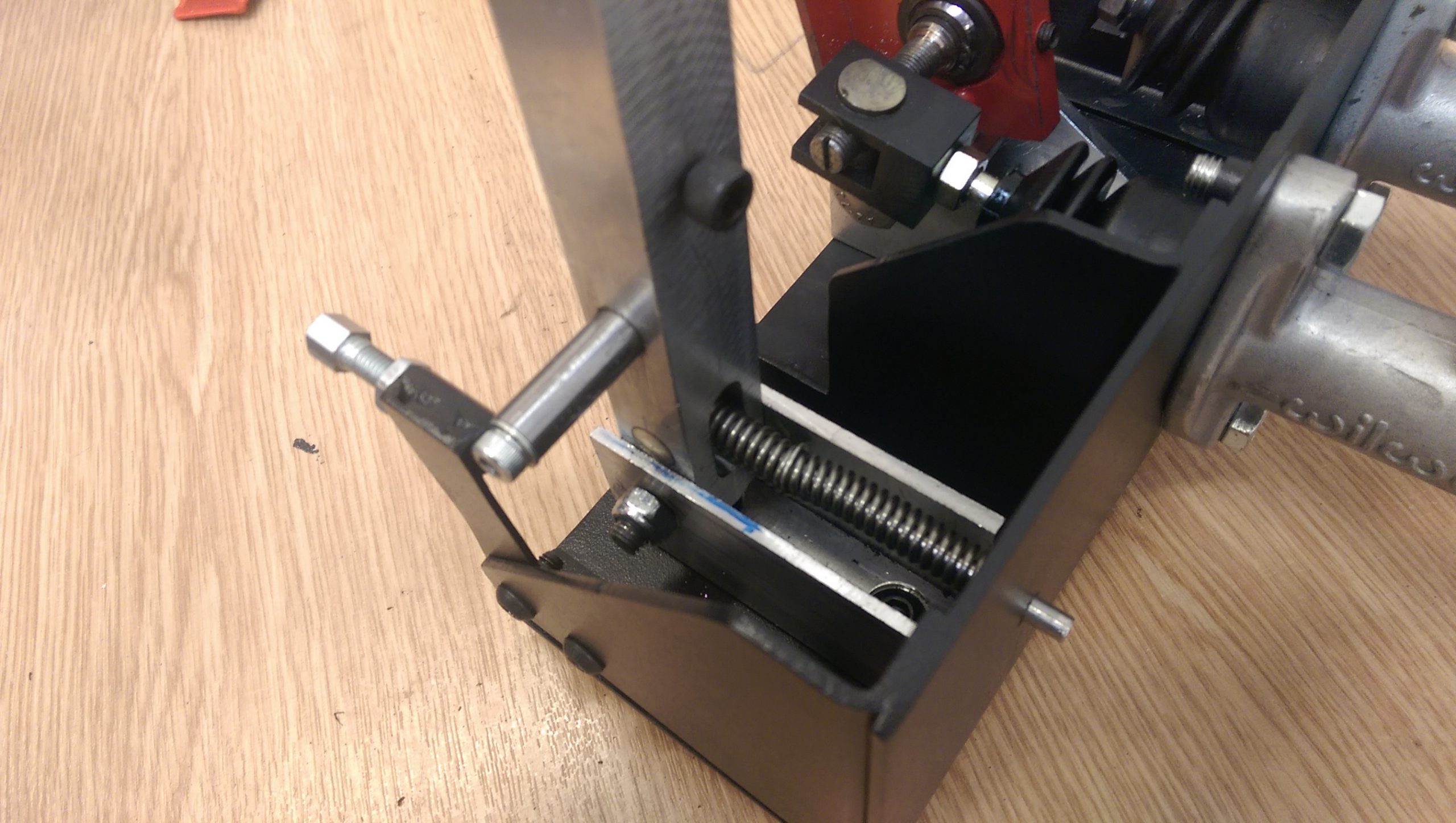
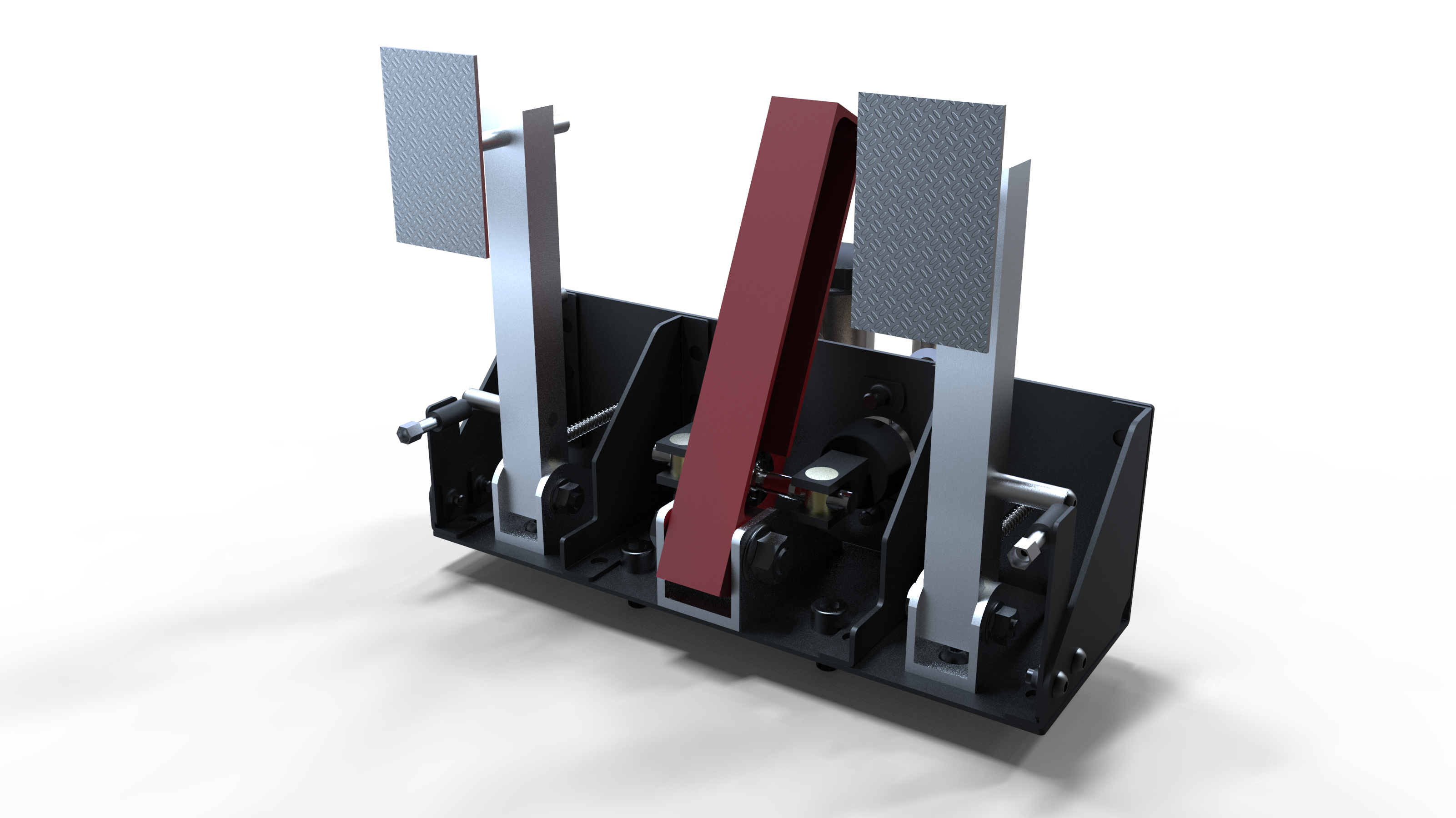
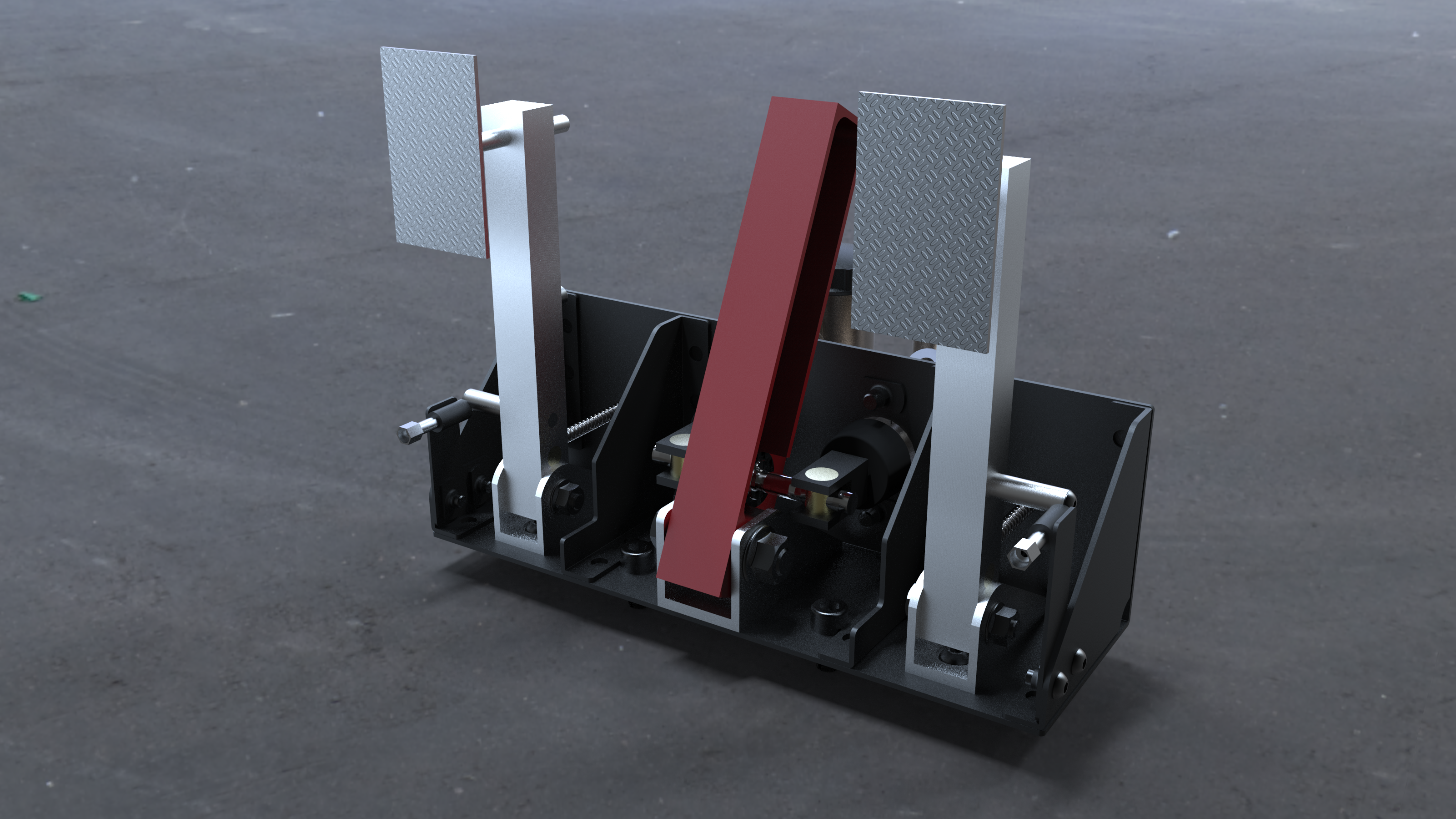
During the summer after the event, I modified the existing pedalbox and improved the way in which the cables were actuated. The box was laser cut out of 3mm mild steel, this eliminated any possible flexibility, even under the test load of 2000N. Modifications were also made to allow for easier assembly and adjustment of the throttle and clutch cables. When installed back in the car, there was a noticeable difference in the stiffness of the brake pedal, all four wheels locked up with minimal brake pedal travel.

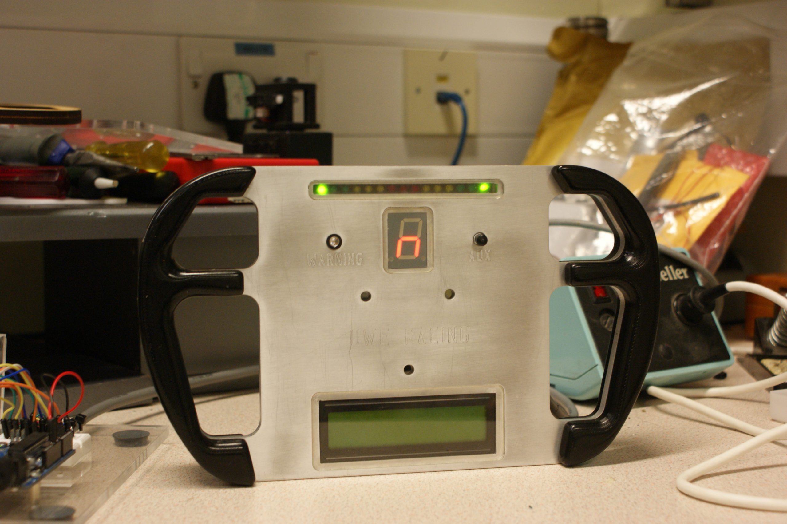
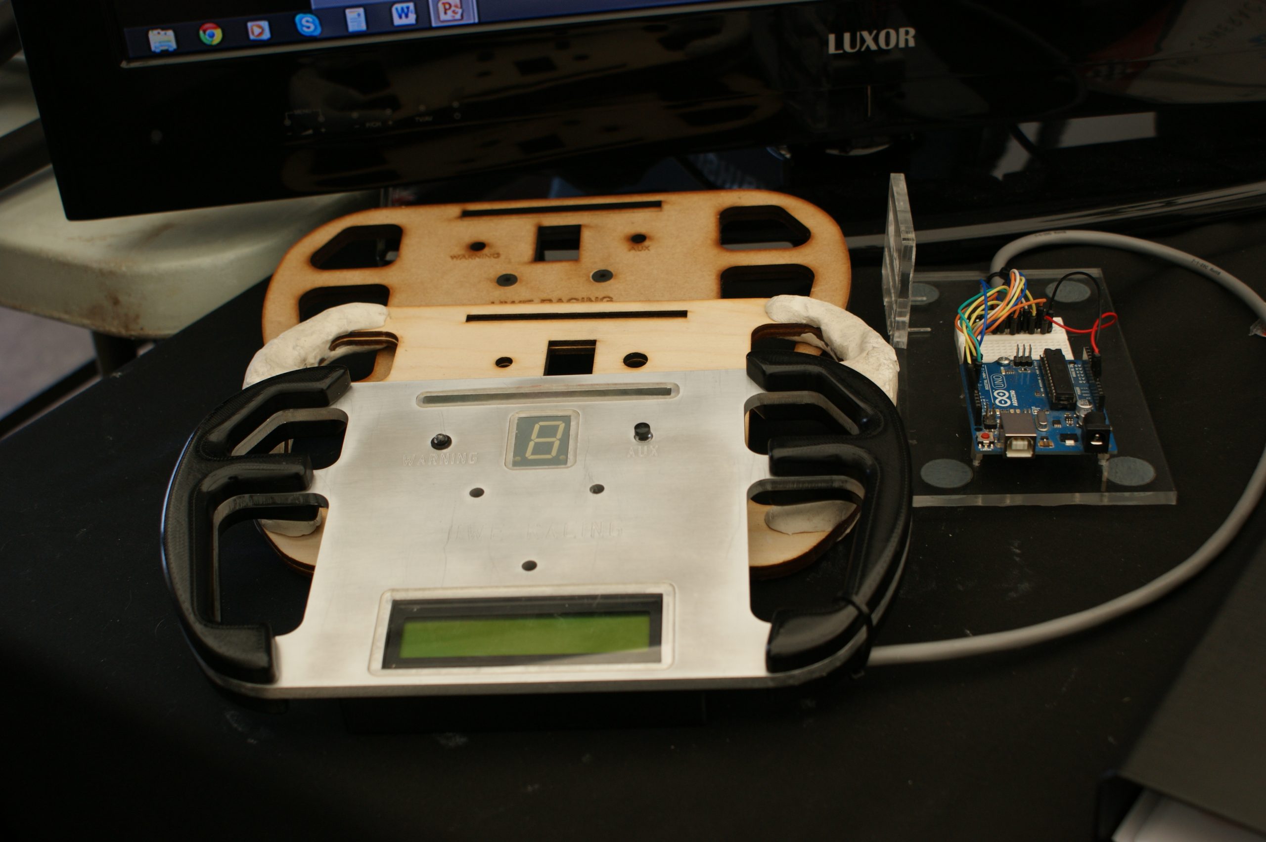
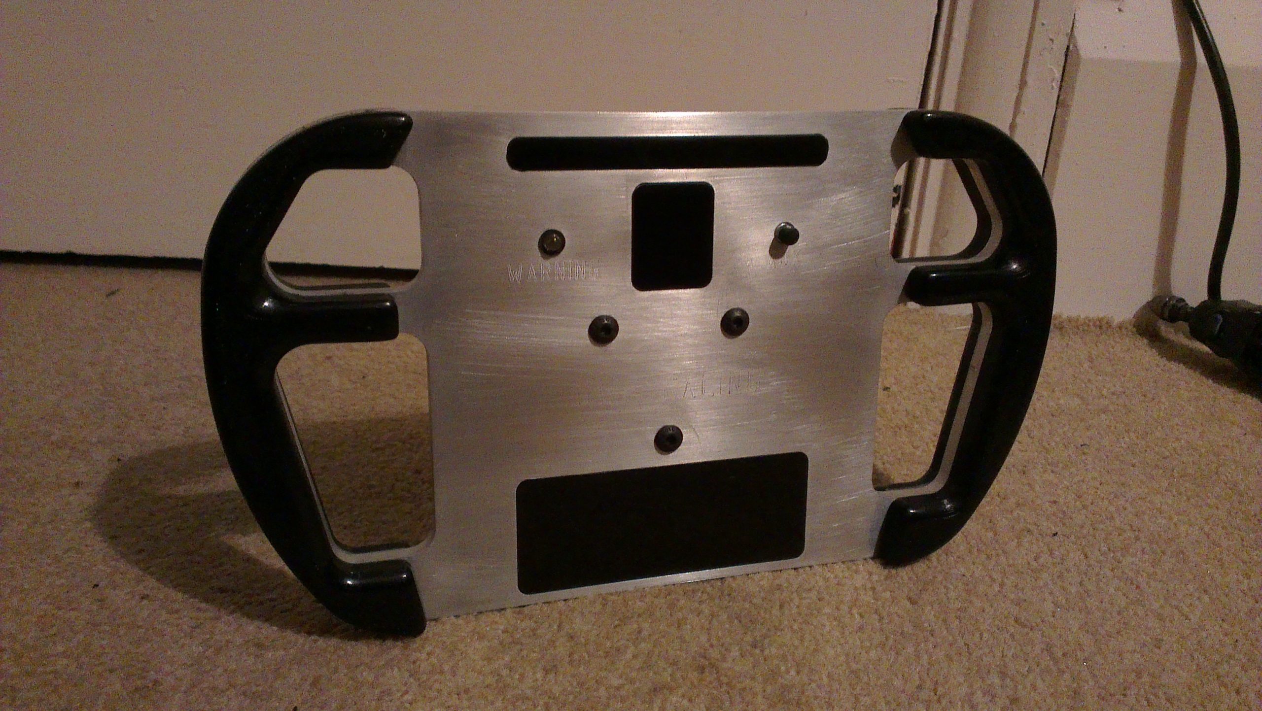
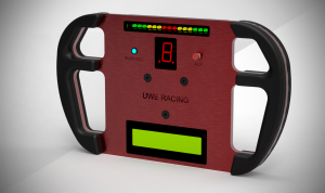
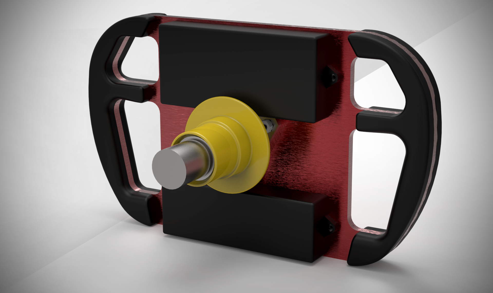
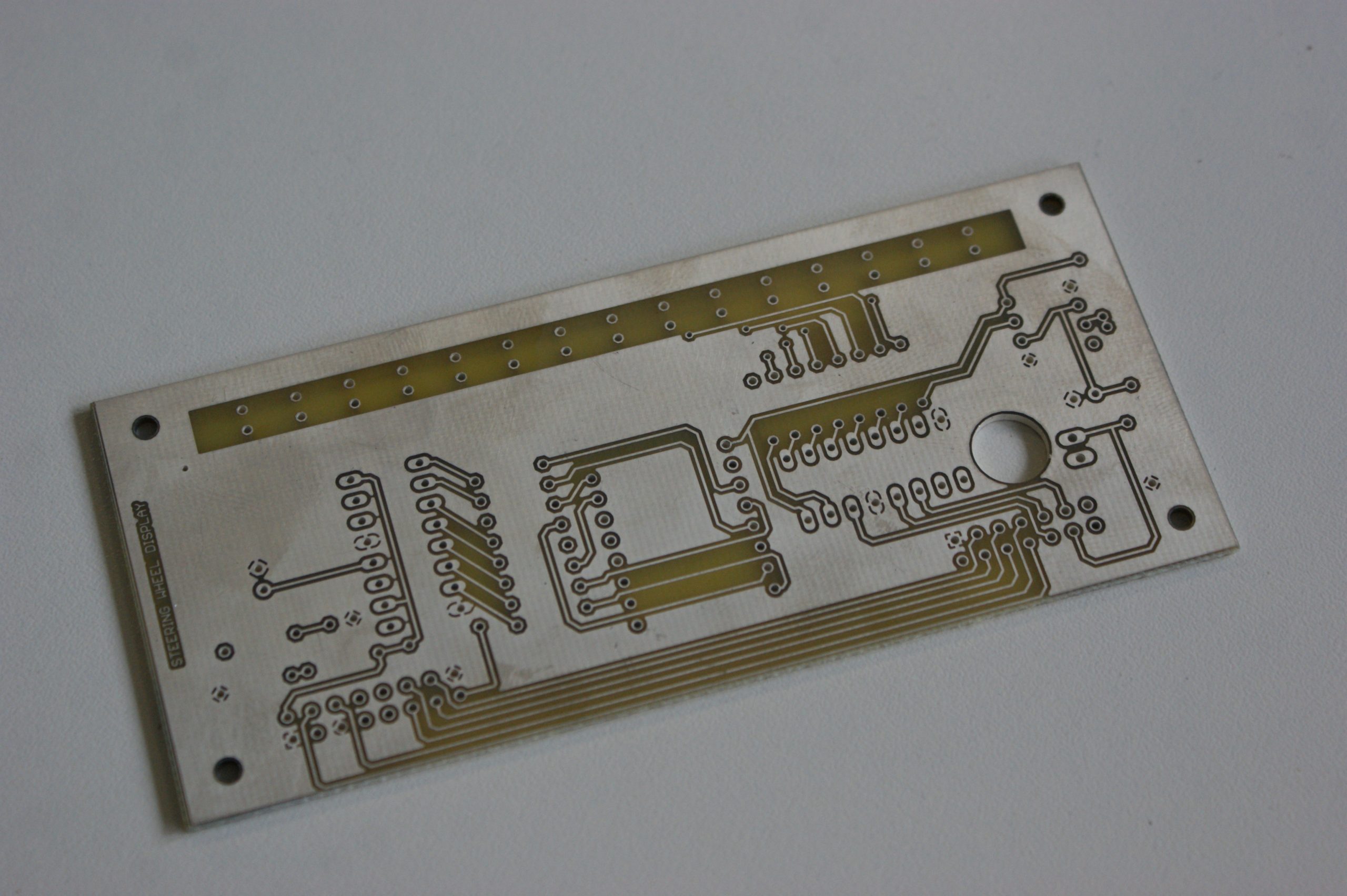
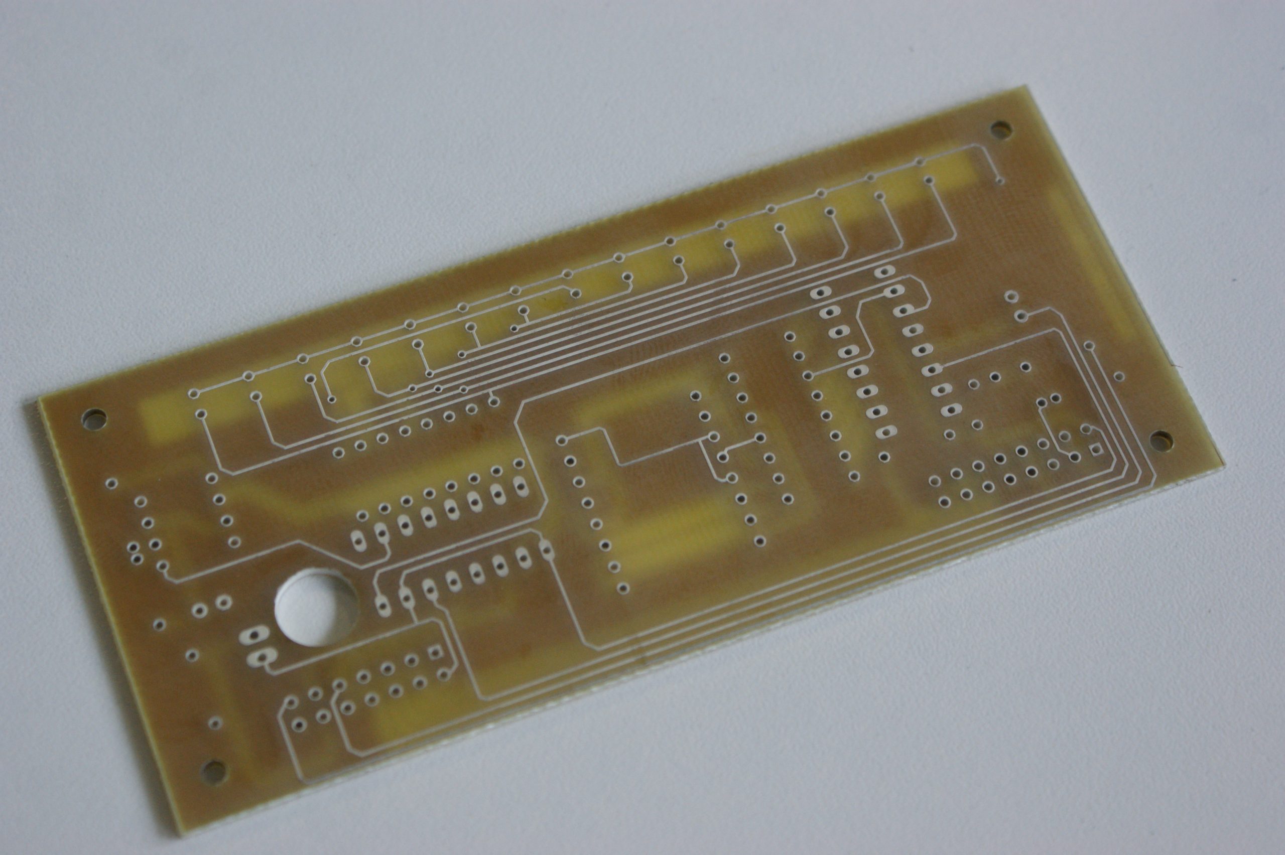
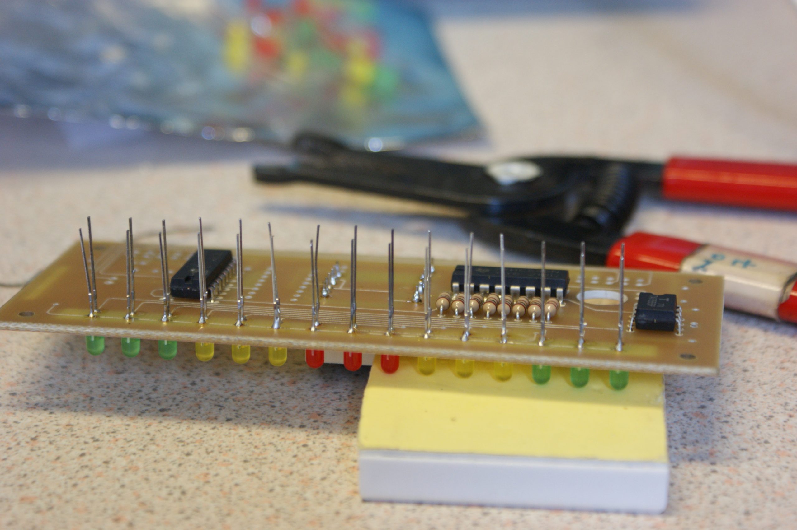
I have made the files for both the electronic steering wheel and the pedalbox available on Grabcad. I hope they will be of use to Formula Student teams looking for inspiration or hobbyists looking for a fun project.

Grabcad Files

Steering Wheel – Completion

Unfortunately the assembly of the steering wheel had to be rushed. This was in order for it to be finished in time for the formula student event last year. Even though it was not quite complete, we still took and displayed the model. Alongside the other prototypes it attracted a lot of attention and provided topics for discussion with the judges.

During some free time after the event, the steering wheel was cleaned up and vinyl tint was applied to the display covers. It will now act as a display model for future events. The model is popular as it can be picked up, handled and inspected closely quite unlike a CAD model.

The team this year will hopefully progress with the experience that was obtained by building this for the first time. There was many mistakes in both design and manufacture that can now be easily overcome with foresight and planning.

Launch Event Display
Steering wheel on display alongside other components at the launch event

Keyshot was used to render views of how the steering wheel could of looked if it was complete and functional. The software allowed for easy selection of material properties and lighting conditions. The outcome is a professional and realistic render.

Keyshot render of the front, red anodised base plate with all displays lit
Steering Wheel Rear Render
Keyshot render of the rear, electronic covers and quick release boss

Finally, even though the event was last July, I have now finished blogging about the design and manufacture of the steering wheel project. I will still be involved with Formula Student for another year so expect more posts in the future.

Now for the next project…

Steering Wheel – Electronic Design and Assembly

The task of designing the PCB, to be mounted to the steering wheel assembly, proved to be tough. With only some experience from GCSE electronics, this part of the project was accompanied with a steep learning curve.

Through recommendation on a number of Arduino forums, the software of choice was Eagle v6 from CadSoft. This is a powerful tool with an extensive library of electronic components. The user interface wasn’t the most user friendly, instead relying on keyboard shortcuts. Although it was easy to learn by following a selection of YouTube tutorials by Jeremy Blum.

The size of the board (51mm x 110mm) was dictated by the space available between the top of the steering wheel and the steering boss, leaving adequate clearance for covers. Placement of the display components upon the board were already decided. This left only the other electrical components and tracks to be placed and routed.

The board was fabricated by Spirit Circuits and their free 48-hour prototyping service “Go Naked”. They provided us with a two sided aluminium coated board with just the essentials, tracks and holes. Their customer service was exceptional in helping to meet our needs. We promptly received a professional high quality board that only required cutting to size prior to use.

Initially the assembly and soldering of the electronic dash went to plan, with the majority of the components fitting without a problem. A couple of overlooks included; attachment of the switch and warning LED, placement of the ribbon cable and selection of connectors.

When linked to the Arduino and powered for the first time, all of the display lit up and ran through the start-up test routine a few times. But before too long, it was noticeable that the display was not functioning entirely correctly. The central RPM range LED failed to blink and the LCD display would occasionally flicker with random characters. This suggested that either a faulty component had been used or the board was shorting. After inspecting the soldering and replacing components, it was found that a grounding fault was the cause. Although it’s exact location was unknown.

While it was disappointing that the display did not work correctly. It proved to be a great prototype and provided us with a number of improvements for the next revision. The main points being; bigger tracks, pads and clearances along with smaller components.

Next… Steering Wheel – Final Assembly

Personal Portfolio